How to Replace the Radiator in a 2004-2010 Toyota Sienna
I wrote this step-by-step tutorial on how to replace the radiator on a 2004-2010 Toyota after I discovered that the overflow tank on my Sienna was empty and then noticed the crystallization of the anti-freeze on the one corner of my radiator and knew it was time for the radiator to be replaced. I’ve always heard (and it makes sense) that you should replace your hoses as well, if you are going to replace the radiator and since you are in there and have half the connections off, you might as well spent another ~$50 and put new hoses on so you don’t run into problems down the road. I’m going to go ahead and swap out the thermostat while I’m at it and that’s only a $16 part (and don’t forget to replace the thermostat’s gasket too).
How to Replace Radiator on 2004-2010 Toyota Sienna
If you would rather have a Toyota Brand Radiator here are the links for the various different years and tow packages from toyotapart.com: 16410-YZZAX -standard radiator for 6-cylinder Siennas manufactured 6/2005-9/2005 16410-YZZAW -standard radiator for 6-Cylinder Siennas manufactured 9/2005 and onward 16041-0A402 -standard radiator for a 6-Cylinder Sienna manufactured from 1/2003-6/2005 (with tow package) 16041-0A403 is the standard radiator for a 6-Cylinder Sienna with the tow package manufactured from 4/2004-6/2005 16041-0A380 is the radiator for 6-Cylinder Siennas without the tow package manufactured from 9/2005 to the end of the model production in 2010 16410-0P160 radiator for 4-Cylinder Siennas manufactured from 12/2006-5/2007 16410-0P161 for the 4-cylinder From 5/2007 onward
12.4 US quarts of Toyota Super Long Life Coolant (if you completely drain the cooling system)
Radiator Hose Clamp (if yours were corroded like mine–you may need from 1-4 of them depending on the condition of yours, only 2 of mine needed replaced)
Fram CA9360 Extra Guard Rigid Panel Air Filter (you must remove the breather box so you might as well replace the engine air filter while you are in there–no point in reinstalling a dirty air filter)
Bent Nose Pliers
(for removing hose clamps if you have spring clamps on them)
A large sheet of cardboard–it’s much more comfortable to lay down on cardboard than a concrete floor (and warmer too!). The box of your replacement radiator should do fine.
Dremel Tool (A VERY handy tool if you need to cut off both rusted lower radiator bolts like I did)
To get the right radiator you need to know the date of manufacturing for your Sienna.
The manufacture month and year can be determined by looking on the driver’s side door frame:
Location of Sticker giving the manufacturing month and year
The sticker is right by the interior lights button:
Location of the van’s manufacture date
Below is a time-lapse video of me doing this repair, in 3 minutes and 9 seconds, from our surveillance camera. The repair took me all day but I ran into unexpected issues which I tell you all about so you can be prepared. I also took over 750 pictures for this tutorial while doing the repair and that takes a lot of extra time so with my help you’ll have your radiator replaced in much less time!
A Bit of Encouragement:
I looked around on the internet and found other tutorials on how to replace Sienna radiators but all of them skip many steps. That drives me nuts. This tutorial doesn’t skip steps. I don’t tell you to “take off the bumper” and then jump to the radiator removal like the youtube videos do, I walk you every step of how to do it. If you are good with your hands, have some common sense, and can follow directions, then you can do this repair with my help. I have over 200 pictures, illustrations, and even hand-drawn (by me) diagrams detailing every step–and once you have the old radiator out I don’t say “follow the steps in reverse” but I personally walk you through the re-installation of the new radiator and all the tips necessary to make this a doable repair. Here are some of the many comments you can read at the bottom of this article:
John Mueller – you are the MAN. I read through your guide several times before attempting the radiator repair. When I got into the job I knew exactly what needed to happen next. The repair was smooth and – most importantly – the van works now! Thank you, thank you, thank you. -Darrell S.
Best step by step, bolt by bolt tutorial I have ever seen. Thank you! I can not imagine how many hours putting this together took. The pictures make it crystal clear, no question about what you are referring to. Amazing attention to detail. Thanks again! -Karl
Many thanks for these super-detailed instructions. The pictures you posted really helped explain what needed to be done. -Alan
Great instructions; thanks so much for all the time you saved me. -John
Thank you for posting such detail instructions. I replaced the radiator on my 2006 Sienna today with the help of your posting. Was taking my time and took me 7 hours to complete. -Ben C.
BURN WARNING: You will want your engine to be cool before you begin this repair. The cooling system is a high pressure, high temperature system and opening the radiator cap before the engine has had time to cool will cause steam and high pressure hot antifreeze to come spraying out and sever burns can occur. If your engine is hot when you start you have quite a few steps that you can do first, in removing the bumper, etc, to give your engine and the antifreeze in the radiator time to cool.
I consulted the official Toyota Repair Manual (RM1163U) in doing this repair but their descriptions and order of steps differ from what I’m going to suggest.
Step 1: Drive your van up on ramps.
I purchased these ramps, which are a pretty good deal and they stack up for easy storage. You could probably do this repair without ramps but it would be pretty tight crawling under your van without that extra space. One thing to note: don’t turn your wheels at all when you are driving up on them because the ramps will turn with your wheels (I know from experience)!
Toyota Sienna up on ramps
Step 2: Remove the black plastic panel that is under the bumper.
I start with this step so you can start draining your coolant while you are taking off the bumper. This panel is what protects the engine from rocks bouncing up and hitting it. I cannot even find this piece in the repair manual but this is what it looks like and most of the screw locations:
Screw locations of the black plastic panel under the engine
There are around 12 possible locations for 10mm headed screws you will need to remove to take off this panel. On my van some of the screws were missing on it, the front edge wasn’t tucked under the bumper like it should have been, and I even had some zip ties holding it in place at one spot. So you’ll just have to look around. This is what it will look like when you get it off and the places there may be screws attaching it to your van (looking at it from the top side):
Lower plastic panel screw locations
Step 3: Start draining the coolant.
There are three coolant drain cock plugs. Honestly, I got busy and didn’t even mess with the two drain cock plugs on the engine but just drained the radiator and then the antifreeze that drained when I changed the thermostat. The diagram supplied in the manual really give you almost no help as to finding them or what they look like exactly.
Radiator cap, drain plug, and drain cock plug locations
You will access the radiator drain plug by looking under the passenger side end of the radiator. Since you have the lower cover panel off (Step 2) you can easily access the radiator drain plug. The drain isn’t like a oil drain plug but more of a faucet-type drain were you turn the knob and the fluid drains out a spout. There is a hole in the bumper to allow for the antifreeze to drain straight down, through the hole, and into your bucket. Position your large pan under the drain and then open it up. This is what the drain plug looks like from the back side of the radiator:
Radiator drain plug location
After you have the drain plug open you would ideally want to open the two Drain cock plugs and the radiator cap to allow air to be drawn into the coolant system while the antifreeze drains out. That didn’t happen for me.
Engine coolant draining from the radiator drain plug
One tip I read was that you should put your hand over the radiator cap (or just leave the radiator cap on) and the vacuum created by the radiator draining will suck the coolant overflow tank empty. I tried this and it really did work:
Holding my hand over the radiator cap while the coolant was draining
When the overflow tank emptied I could feel a blast of air as the system began to suck air (instead of coolant) from the coolant overflow tank. At that point I took my hand off the cap.
Step 4: Remove the Air Cleaner Inlet.
You will need to disconnect one wiring connector (VSV connector), free the wire harness clamp, and then remove the 2 bolts on the front edge of the inlet housing. Here’s what the air cleaner inlet looks like and the locations of the steps:
Air cleaner inlet
The VSV connector has a tab on the bottom of the connector that you must press in while you pull the connector free. I was not able to pull it free with my fingers so I used a screwdriver and twisted as seen below, prying the connector loose while pressing the tab:
Prying VSV connector free while pressing the tab with my fingers
VSV connector and clip details
This is what the connector looks like when you get it disconnected:
VSV Connector Removed
Pry the wire harness clamp free in the direction of the arrow with a large flat-head screwdriver:
Wire harness clamp on air cleaner inlet
Here the wire harness clamp is free
Now remove the two 10mm bolts from the front edge of the air cleaner inlet housing:
Removing the first of 2 air cleaner inlet bolts – 10mm socket
Now you can remove the air cleaner inlet. Lift the front edge up and pull it towards you while moving it back and forth (left/right) to disconnect it from the air cleaner assembly. This is what it will look like when you get it removed:
Air cleaner inlet removed
Step 5: Remove the air cleaner assembly top cover.
This will involve disconnecting the mass air flow meter connector, disconnecting 3 vacuum hoses, loosening the two air cleaner cap bolts, and then removing the cover.
Overview of all the steps to removing the air cleaner assembly top cover
Press the tab down and pull the mass air flow meter connector out:
Disconnecting the mass air flow meter connector
Mass air flow meter connector removed
Air cleaner assembly details
Pull off the three vacuum hoses. They should come off easily by hand.
Air Cleaner vacuum hoses
I labeled mine with tape before I removed them so that I was certain as to which one goes back on which nipple:
Vacuum Hoses Labeled
Loosen the two air cleaner cap bolts. They are retained by the cleaner cap so they will not come out. They are pretty long so you’ll have to ratchet for a while. They have a 10mm hex head on them. You’ll need a socket extension to reach the back one.
Removing the front air cleaner cap bolt
Loosening the back air cleaner cap bolt
Loosen one or both of the air cleaner hose clamps. I tried loosening the back one and I couldn’t get the hose to come off so I loosened the closer one and then with the aid of a flat head screwdriver was able to get it to slide off:
Prying the air cleaner hose off
Note that there is a lip on the end of the air cleaner cover pipe that wants to keep the hose on there:
The air cleaner upper assembly is freed from the hose
Then remove the air cleaner cap:
Air cleaner cap removed with the filter in it
Step 6: Remove the air cleaner assembly lower box.
There’s a wiring harness snapped into the back of it and then that same wire is clipped into another harness in the back. Once you have the wiring harness removed you can remove the 3 bolts and the box.
Wiring clip details
The wire harness clamp is pictured below. I was able to take a flathead screwdriver and pry it out of its place.
Air cleaner wiring harness
This is what it looks like removed:
Air cleaner wiring harness clamp removed
Then release the wiring cable from the clamp:
Air cleaner box wiring camp removal: Pull the wires out of the clamp in the direction of the arrow
Remove the 3 air cleaner box bolts:
Air cleaner box bolt locations
Remove the air cleaner box. It simply slips out of the lower air pipe it is connected to. If you didn’t completely remove the hose that was connected to the cover it will be in the way:
The upper hose is in the way of removing the air cleaner box
Completely remove the upper hose and then take out the box. It will lift straight up and out. I was careful to put the mass air flow meter cable up and out of the way so I didn’t accidentally cover it up when I was re-assembling things later:
Put the mass air flow meter cable up and out of the way
Step 7: Remove the battery.
First remove the bolt on the bracket that is closest to the front of the vehicle. It is a 10mm hex head. You shouldn’t need to loosen the back one.
Removing the front bolt of the battery bracket
Once you have removed the front bolt put it back in its place so you don’t lose it. If you lift up on the battery bracket’s end that you just unbolted then the rod that hooks into the base of the battery pan will come out and you can remove the battery bracket:
Removing the battery bracket
Loosen the bolts on the positive and negative battery terminals. Here’s the nut you loosen on the positive terminal:
Positive terminal nut location
And the negative terminal:
Postive terminal nut location
Lift the battery cable connectors off the posts of the battery and the lift the battery out of the van. The pan that the battery sits on will lift right out:
Removing the battery pan–it comes right out after you remove the battery
Step 8: Remove the air cleaner bracket.
Remove the two bolts from the air cleaner bracket and set it aside (put the bolts back in their holes for safe keeping):
Air cleaner bracket bolt locations
Step 9: Remove air cleaner inlet number 1.
There is one bolt on the front end of it that you must remove:
Air cleaner inlet number 1 bolt location
After that bolt is removed you can lift the inlet right out. The inlet does slip into a white box but it comes right out easily.
Air cleaner inlet number 1 removed
Now you have a hole in your engine bay:
Gaping hole in engine bay
Step 10: Disconnect your radiator hoses.
You wouldn’t have to do this at this point but this is what I did now. You may have different types of hose clamps than mine. Two of mine were the squeeze type and two were the screw to tighten type (on the radiator ends). Both of the screw-type were in need of replacement. Here is the upper radiator hose:
Upper radiator hose
After loosening the hose clamp I used a flat screwdriver to pry the hose loose. It was stuck in place pretty good.
Prying the radiator hose loose
There’s no way I was going to put this hose clamp back on my van:
Corroded hose clamp–I will definitely not put that back on my van
Location of the lower radiator hose along with the two oil cooler hoses:
Radiator hoses on the drivers end of the radiator–2 oil cooler lines and the outlet water line
Here’s the view of the lower hose from below. Loosen the hose clamp and the twist and pull the hose off. Be prepared to catch the remaining antifreeze in the radiator when you pull off this lower hose:
Lower radiator water hose, view from below looking up
After I removed the hose clamp I had to use a screwdriver to pry it off. If you are replacing the hoses like I am you could just use a carpet knife and cut them off too. I thought about doing that but something inside me just didn’t want to destroy them even though I was going to throw them away anyway.
Prying off radiator hose with a large flat screwdriver
Lower radiator hose off–I got a bit of a face-full of antifreeze when that hose broke free
First move your catch pan underneath the location of the oil cooler hose connections. Using a pliers squeeze the hose clamps and move them onto the hoses on the oil cooler lines and be ready to lose a little oil too so keep the ends up high when you disconnect them.
Oil cooler hose clamp locations
Here the hose clamps are removed and pushed back on the hoses:
Oil cooler clamps removed
Before trying to pull the oil cooler hoses off first free them from the harness they are held in place with:
Oil cooler hose harness
They slip right out:
Removing the oil cooler hoses from their harness
Here they are removed:
Oil cooler hoses removed (and oil leaking from the lower connection)
I put the one oil cooler hose through the positive battery cable to keep it “up”:
Holding the oil cooler hoses up so they don’t leak oil
Step 11: Remove the front bumper.
This was the hard part for me but I’m going to make it easy for you. I couldn’t fine ANYONE on the internet telling you how to do this step by step. Here’s how to do it…
Bumper details
Step 11a: Pop the centers out of the two clips on the front end of the wheel well of both bumpers.
One of my readers commented that you should insert a flat-head screwdriver into the center and turn it so it is parallel with the clip (or with the edge of the wheel well) and then pry them out. They may come out easier if you do that but I have not tried it myself. I read all the comments on this site and appreciate everyone’s feedback.
Take the centers out completely and set them in a secure place. At first I didn’t take them all the way out (when I took the picture below) but I had to later. Be careful, they seem to be fragile although none of them were broken when I took them apart (unlike the ones in the front middle of the bumper on top).
Pry up and remove the centers of the two clips on the front edge of the wheel well
Here’s what they look like removed:
Center removed from wheel well bumper clip
Step 11b: Remove the 5 clips from the top front of the grill.
Front bumper grill area clip location
Pry the center up (but not necessarily out) first:
Prying the bumper clip center up
After you have popped out the center pry up the outside to remove the clip:
Prying out the unlocked clip
This is what they look like when you get them out:
Grill Clips Removed
Two of them were shattered when I got them out so I had to replace them.
Step 11c: Remove the screw from the far ends of the lower edge of the bumper.
This is a phillips head screw (and I believe 10mm hex too) and is right in front of each tire:
Lower corner bumper screw
Step 11d: Remove the two white square plastic snap-in plugs from the lower left and right corners of the bumper.
This is what they look like:
White square plastic snap-in plug
This is what they look like when you get them out:
White square plastic plugs removed
Step 11e: Remove the bumper from the clip you removed the screw from in Step 11c.
Some of these were a little tricky for me because some of these clips have a little tab you must lift up from the back side in order to get the clip to release the bumper (even though you removed the screw or popped the center out of the clip. If necessary reach around to the back and lift the tab on the clip and then pull the bumper free.
Releasing the lower corners of the bumper
Here’s a close up of the bracket with the tab on it:
Lower Bumper clip brackets with tab
Here’s a look at this clip, removed from the van:
Clip Close-Up
Step 11f: Disconnect the wiring harnesses from the left and right fog lamps.
You’ll need to look from the underneath side of your bumper for these. Make sure not to pull on the wires but pull on the plastic connector (you can pull the wires out). This is how you remove them:
Fog lamp wiring connector removal
Here’s what they look like removed:
Fog lamp wiring connector removed
Step 11g: Disconnect any other wiring harnesses you see connected to things on the inside of the bumper.
You may need to disconnect other wiring harnesses at this point too if you have the smart key system or the automatic cruise control that detects that you are approaching another vehicle–there are radar sensors behind the bumper that you’ll need to disconnect at this point as well.
Step 11h: Tape the seam of the bumper.
Because we are going to be prying in the seam it is not a bad idea. I used plane masking tape and put down a couple layers and made it wrap around the corner at the seam too:
The seam between the bumper and quarter panel taped
Step 11i: Unclip the 3 tabs on each side of the bumper to release it from the quarter panel.
This might have been the hardest step to figure out on this whole repair and I couldn’t find anyone on the entire internet who would tell you how to do it. I didn’t want to break these clips so I was very cautious but finally figured it out. Here is a video of me releasing them and then read on for the step by step instructions:
Here’s a picture with the bumper unclipped so you can see what we are trying to do:
Bumper clip tab
I pulled down on the bumper to slightly, grabbing it from the wheel well edge, to make the seam bigger. Start with the snap that is closest to the wheel and use a thin flat-head screwdriver wrapped with one layer of electrical tape. Locate the “holes” in the bumper, which indicate there is a clip there and insert your screwdriver as seen in the diagram below (as seen looking straight on):
Bumper Clip Release Diagram
First clip released
Releasing the second clip
All released:
The bumper clips have all been released
In order to help myself find the clips on the second side I measured where they are located from the front edge of the bumper They were located at approximately 1 1/2″, 5 7/8″, and 10 1/2″ from the front edge of the bumper as seen below:
Clip location measurements
Once you have both sides unsnapped you can remove the bumper. I simply picked it up from the front top, in the middle, and set it aside.
Bumper Removed
Step 11j: Remove the styrofoam insert.
It is just pushed into a couple holes of the metal frame of the van and comes right out. Here’s the pile of parts I’ve taken off so far:
Pile of parts
Step 12: Disconnect the horn wiring harnesses and remove the hood latch.
Here’s an overview of the important areas:
Overview of important areas
You must remove the plastic hood lock release lever protector. It has 4 places where it snaps into the van. I was a bit perplexed as to how to release the top snaps (the top right and top left circles in the picture above. I took a picture from the back:
Hood lock release lever protector top clip
The easiest way to release those top clips is to squeeze in the sides on the back side with a bend needle nose pliers. Here’s a look at the top clip when you get it off:
Hood Lock Release Lever Protector top clip removed
Once you get the top ones released you can just pull off the bottom ones because they come out easy. Here’s a view of one of the two lower clips:
Lower clip
Here’s the plastic cover removed:
Hood Lock Release Lever Protector removed
Once you have the cover off you can remove the three bolts from the hood lock release:
Hood Latch bolt locations
Disconnect the hood latch wiring connector. There is a tab you must depress in order to retract the catch that keeps the connector in place, push where you see the arrow pointing down:
Hood latch wiring connector
One thing to note is that there is also a cable running to the hood latch assembly so you will just need to find a place to set it aside within range of its cable tether 🙂 I set mine on the right on what is left of the metal bumper:
The hood latch setting on the bumper, still tethered by the hood release cable
Here’s a close-up of the horn wiring connectors. Press in the tab and remove the connector on both horns:
Horn wiring harness release tab
Horn Wiring Connector Removed
I actually removed the horns at one point to give me better access to the plastic cover so remove them if you need to.
Remove the cable clip and what I believe is an air bag sensor that snaps into the metal bumper:
Air Bag sensor and cable clip locations
The sensor has a very similar clip that holds it in place that can be simply pried up with a flat-head screw driver. I forgot to take a picture of it but it’s really easy to disconnect.
Step 13: Remove the upper radiator support sub-assembly.
There are 2 bolts on each side and then one in the middle:
Upper radiator support bolt locations
Here’s what it looks like when you get it removed:
Radiator upper support assembly
Step 14: Disconnect the engine coolant reservoir hose.
The hose needs to be released from a little clip on the side of the reservoir:
Coolant reservoir overflow hose clip
Squeeze the hose clamp with your fingers and push it onto the hose and out of the way:
Coolant reservoir overflow hose clamp–squeeze and put onto the hose
Twist and pull the hose to remove it from the reservoir tank.
Reservoir hose removed
Step 15: Disconnect the clip of the wiring harness that goes up and over the radiator.
I used a needle nose pliers to squeeze in the sides of the “catch” that connects it to the radiator:
Disengaging the clip holding the wiring harness on top of the radiator
Step 16: Disconnect the fan wiring connector.
There is a tab on the driver’s side of the connector that you must squeeze in to release the connector before pulling it off.
Fan wiring connector
Here I am pressing in the tab:
The Fan wiring connector removed
Now that you have all the connectors disconnected, set this wiring harness up on top of the engine and out of the way:
Wiring harness laid up on the engine, out of the way
Step 17: Disconnect the wiring harness clips from the fan shroud and van body on the driver’s side of the radiator.
Simply pry the connector out with a flat-head screwdriver:
Wiring harness connectors
Here’s what the one looks like that was in the fan shroud when it’s removed:
Wiring harness clip removed
Step 18: Remove the 4 bolts from the fan shroud.
They are located on the engine side of the shroud on the 4 corners. I used a 5/16th hex-head socket to remove these. Here are pictures of the 4 bolts (and when I say right or left it is using the left side as the driver’s side):
Top right fan shroud bolt location (already removed)
Top left fan shroud bolt location (already removed)
Bottom right fan shroud bolt location
Bottom left fan shroud bolt location
Step 19: Remove the 2 brackets from the top of the radiator/condenser assembly.
Note: you will need to re-use these two brackets and the bolts holding them on. There is a phillips head screw that goes through two brackets–an outer one that overlaps both the radiator and condenser and an inner one that sits inside the top of the condenser:
Bracket that overlaps the radiator and condenser
Once you remove the phillips-head screw you can lift the outer bracket straight up and off to reveal the smaller bracket on the condenser:
Condenser bracket that is hidden under the other bracket
The condenser bracket will just lift off. You can leave it sitting on top of the condenser because the condenser is not going anywhere. One thing to note is that there are brass clips that remain on your old radiator at this point that you will need to carefully pry off and re-use on your new radiator. There are two on each side:
These are the brass clips that the radiator bracket bolts screw into
Step 20: Remove the fan shroud.
There is one more electrical connector towards the bottom of the fan that you must disconnect:
Lower electrical connector on fan shroud (from below)
Lift the fan shroud by the top edge and lift it straight out:
Fan shroud removed
Here’s what it looks like at this point, time to get this radiator out of there:
Getting close to having that radiator out of there
Remove the lower bolt from the vertical radiator/bumper support bracket. It is the bracket that is right in the middle of the radiator in the picture above.
Removing single bolt on bottom end of vertical support bar
Step 21: Remove the two lower radiator brackets.
Here’s where I ran into a problem. The lower two brackets are very similar to the top ones and held in place by a phillips head screw. Mine were totally rusted:
Passenger-side lower rusted radiator bracket
Driver’s side lower radiator bracket–totally rusted
I tried loosening the phillips-head screws on the lower brackets but there was not a chance in the world they were going to unscrew–they were rusted to the bracket. First I tried to unscrew them and they didn’t budge. Then I tried to spray them down with WD-40:
Bolts on lower radiator brackets soaked in WD-40
At this point I decided to grab my Dremel tool with cutting disks and cut off the brackets. I wish I would have known I was going to run into this problem so I could have ordered new brackets but I was at the point of no return so we were going to get that bracket out of there. Safety Note: You should definitely use safety glasses when using a Dremel-type Rotary tool. First I tried grinding a slot for a flat-head screw driver:
I’m about to cut a slot in the head of the screw
Trying a flat-head screwdriver to remove the rusted screws
Using a Dremel Tool on the left bracket
On one side I ended up cutting all the front face of the bracket off. Do remember that the condenser is right there, which we are NOT replacing, so you don’t want to damage it. If you grind a bit on the lower lip of it, it won’t matter though.
Bracket face cut off with Dremel Tool
Then I used a vice grip on the head of the phillips-head bolt and removed it:
Using a vice grip to remove the bolt
Remove the bolts from the underneath side of the lower brackets on each side. I used a 5/16th Socket. I was able to lift the radiator/condenser assembly up and out of where it is located to give me room to get a socket wrench on the bolts. The condenser lines give you some room to move things around:
Lower radiator brackets lower bolts
Removing the lower bracket bottom bolt
Here’s what the bracket(s) look like when you finally get them off:
Lower Radiator Bracket Removed
One of the lower brackets stayed on the condenser but that doesn’t matter since the condenser is staying put:
Lower bracket that stayed on the condenser
Step 22: Replace the upper (passenger side) radiator hose.
I actually did this while I was trying to soak the lower radiator bracket screws in WD-40. Pop the overflow hose out of the plastic clip and squeeze the hose clamp and push it back on the hose (or unscrew it if you have the screw type). Twist and pull the radiator hose off.
Passenger side radiator hose
Hose removed
You’ll need to transfer the overflow hose clip to the new hose. I broke this plastic part while trying to remove it. You can learn from my mistake.
Overflow Hose clip removal instructions
I broke off the two tabs when I removed mine (circled in red):
Plastic “catches” that broke off
Install the new radiator hose. I put some spit on the inside of the hose to get it to slide on easier. This makes a big difference (I found out the hard way and couldn’t get one of the hoses on and then had a really hard time to get it off so I could wet the rubber to get it to slide on easier). There is a tab that shows you how far it needs to go on:
New Passenger-side radiator hose reinstalled–push all the way till it runs into the tab that sticks up
Put the hose clamp back in place. The hose camp should be half way between the end of the hose and where the ridge is around the end of the aluminum pipe you are slipping it on (or half way up the yellow line painted on the hose):
Hose clamp back in place on new hose
Put the overflow hose clamp back in place–there’s a white line to indicate where it should go on OEM Toyota hoses. I used a couple zip ties to hold it in place since I broke mine.
Step 23: Remove the old radiator.
At this point it should lift straight up and out of the van. This is what it looks like out:
Old radiator out of van, whew!
Step 24: Transfer the brass clips from the old radiator to the new one.
There should be at least one for each of the four brackets. They are what the bolts screw into on the radiator brackets.
Sliding the clip off
Clips Removed
You may need to clean out the inside of the clip to be able to slide it all the way onto the new radiator.
Old clips installed on new radiator
Step 25: Install the lower brackets back on the new radiator.
One of my lower brackets was still connected to the condenser so I only had to install it onto one side at this point:
The way the new radiator was designed I couldn’t put two bolts back into it–so I used a zip tie for one side
I had to ad lib a bit to install the old brackets onto the new radiator. The radiator isn’t going anywhere and there’s not going to be much pressure on any of these brackets so it will be fine. As you can see from the picture above you can see there is only one bolt installed. This is why I wished I’d ordered new brackets to begin with but in reality this will be fine.
Step 26: Install the radiator back into the van.
You will need to lift up the condenser to sit it on top of the bracket(s) that are already attached to the radiator.
New radiator installed in van
If one bracket was still attached to the condenser you will need to lift up the assembly and reinstall the bolt that goes through the bracket and into one of the brass clips you installed in the new radiator.
Step 27: Reinstall the lower bolts that go through the radiator and into the condenser.
In my case I just put zip ties because I had cut away the front flange of the bracket.
Zip tie instead of bolts on the lower brackets
Zip tie instead of a bolt on the lower bracket
Zip tie in lieu of the bolts
Zip tie on other bracket
Step 28: Reinstall the top brackets.
Install the clips on the top side of the radiator (if you haven’t already), the metal brackets that slip over the condenser, and reinstall the top brackets.
Driver’s side
Passenger’s side
I was only able to reinstall one of the two bolts for each bracket but it will be just fine:
Passenger side top radiator bracket reinstalled
Driver’s side top radiator bracket reinstalled
Reinstall the bolt that goes through the condenser (I’m installing new bolts in them):
Passenger Side Condenser Bolt
Driver side condenser bolt
Step 29a: Replace the passenger side radiator hose.
This is just when I happened to do it. You could have done this at some other point. It is located right by the orange transmission dipstick.
Hose clamp for driver’s side radiator hose
Squeeze the hose clamp together and move the hose clamp onto the hose.
Hose clamp moved off the inlet pipe for removal
Twist and pull to remove the radiator hose from the water inlet.
Driver’s side radiator hose removed from water inlet pipe
If you were going to change the thermostat, which I did during this repair, now is when you would proceed to those steps. If you want to change your thermostat, click on the following link and then skip down to Step 7to pick up from where you are and go all the way to Step 12 and then come back here.
If you are not going to change the thermostat then continue on below:
Step 29b: Transfer the hose clamp to the new radiator hose.
Wet the inside of the end of the hose (to make it easier to slip on) and then install the new hose on the water inlet. Make sure to push the hose on so that the white strip is fully on the water inlet pipe. I put a new screw-style hose clamp on the other end of the hose too, since I replace it:
New water inlet radiator hose with the old squeeze type clamp and a new screw hose clamp on it, ready to be installed
Step 30: Reinstall the fan shroud.
Put the fan shroud in place. There are tabs that “catch” on the top of the radiator so it should stay in place while you bolt it:
I’m pointing to the plastic tab on the fan shroud, which overlaps the top of the radiator
Line up the holes on the shroud with the holes on one of the top brackets:
Lining up the fan shroud bolt holes
The bolts have 10mm heads on them. Here I am reinstalling one of the lower bolts:
Reinstalling one of the bottom two fan shroud bolts
Step 31: Reinstall the middle vertical support bar.
There is one bolt at the bottom of it:
Reinstalling the bolt on the vertical support bar
Step 32: The step I forgot: Reconnect the oil cooler lines.
Insert the oil cooler lines on the radiator. Once they are slid on, squeeze the hose clamps and place them back into their original locations:
Push the oil cooler lines back on their pipes
Now slip the oil cooler lines back under the bracket that holds them in place:
Slip the oil cooler lines up under the retainer
Step 33: Run the wiring harness up and over the radiator and snap it into place.
I forgot to do this the first time and had to backtrack!?!? This is the one I’m talking about:
Horn, hood latch, and air bag sensor wiring harness
Reconnect the fan wiring connector:
Reconnecting the fan wiring connector–make sure to get it all the way on
Then the cable snaps into the top of the radiator:
Wiring harness bracket snapped back into the top of the radiator
Step 34: Reinstall the upper radiator support sub-assembly.
This is the part that has the horns mounted on it:
Reinstalling the radiator upper support sub-assembly
Line up the rubberized holes in the assembly with the posts that stick up from the two top radiator brackets:
Line up the posts with the rubber insert
There are two bolts on each side. I had put the bolts right back into their holes when I removed this piece so you may have to remove them to reinstall it (the picture I took before disassembling it):
Bolt locations on upper radiator support sub-assembly
Reinstall the top bolt that connects the vertical support bar:
Location for vertical support bar top bolt
Step 35: Reinstall the hood lock release lever.
Hood lock release lever
You’ll want to have the cable in the correct location, behind the horn mounting tab before you bolt it down.
Bolt locations for the hood lock release lever
Hood lock release lever reinstalled
Reinstall the hood lock release lever protector.
Hood lock release lever protector
First snap in the lower clips:
Snapping in the lower clips first
And then snap in the upper ones:
Upper clip locations
One thing I had to backtrack and change was the path of the hood release cable. I felt like it should go behind the metal mounting tab on the driver’s side horn, as seen below:
Hood release cable path–behind the horn
Step 36: Reconnect the wiring connectors to the hood release lever and the horns.
Reconnecting the hood release connector:
Reconnecting the hood release wiring connector
Reconnect the passenger’s side horn wiring connector:
Reconnecting the passenger’s side horn wiring connector
Reconnecting the driver’s side horn wiring connector
Reinstalling the wiring clip for the air bag sensor on the vertical support bar
Reinstalling the air bag sensor on the bottom of the vertical support bar
Step 37: Reinstall the coolant overflow tank hose.
Reinsert the hose onto the nipple and move the hose clamp back into place:
Coolant overflow tank hose
Insert the hose back into the retainer clip that is built into the side of the tank
Coolant overflow tank hose reinstalled and the hose clamp back in place
Step 38: Reinstall air cleaner inlet number 1.
This is what that looks like:
Reinstalling air cleaner inlet number 1
There is an opening in the bottom of the air cleaner inlet number 1:
Opening on the bottom of air cleaner inlet 1, which fits onto the tank shown below
Tank that air cleaner inlet number 1 connects to
Reinstall the one bolt on the flange of air cleaner inlet number 1:
Bolt location on air cleaner inlet number 1
Step 39: Reinstall the air cleaner bracket.
This is what that looks like:
Air cleaner bracket
It bolts to the holes circled below, right where the battery mounting pan sits:
Air cleaner bracket bolt hole locations
Here it is reinstalled:
Air cleaner bracket reinstalled
Step 40: Reinstall the air cleaner (lower) case.
If there was any sand or leaves in it, make sure to clean it out while you have it out of the vehicle and before you reinstall it:
Clean out your air cleaner lower box before reinstalling
The square hole in the air cleaner case sits down over the end of the air cleaner inlet number one:
End of air cleaner inlet number 1, where the air cleaner box connects
Before setting the box down on the inlet make sure your 3 vacuum hoses and the wiring bracket for the VSV connector are out of the way (and you don’t trap them down below). There are three 10mm head bolts you will need to reinstall:
Bolt locations of the lower air cleaner box
Clip the wiring harness on the back of the box:
Slip wiring harness into the clip on the back of the air cleaner box
Then connect the clip up higher on the air cleaner box:
Snap clip into the upper edge of the air cleaner box
This is what the wiring harness should look like then:
Wiring harness in place on back of air cleaner box
Reconnect the wiring harness on the front left corner of the air cleaner box:
Reconnecting wiring connector on front left corner of air cleaner box inlet
Step 41: Reinstall the upper air cleaner case.
First reinstall the hose if you removed it like I did:
Air cleaner inlet hose reinstalled
Make sure to tighten up the hose clamp. Now reinstall the air cleaner cap. First you’ll want to connect it to the hose pictured above, then you’ll want to install your new air filter. To reinstall the cap you’ll tuck the two fingers that stick out of the left side of the cap into their slots on the lower case:
One of the two fingers that stick out of the cap and tuck into the “catches” on the bottom
Reconnect the mass air flow sensor wiring connector:
Reconnecting the mass air flow sensor wiring connector
Reconnect the three vacuum hoses on the left side of the cap:
Here I have 2 of 3 of the vacuum hoses reconnected
Tighten the front and rear bolts of the air cleaner cap (10mm socket):
Front bolt of air cleaner cap
Tightening the back bolt:
Tightening the back bolt of the air cleaner cap
Step 42: Reinstall air cleaner inlet number 2.
This is what it looks like (from when I removed it):
Air cleaner inlet number 2 for reinstallation
It slips over the opening on the front of the air cleaner box:
This is where the air cleaner number 2 connects to the air cleaner assembly
The the bottom of air cleaner inlet number 2 connects here:
Air cleaner number 2 sits down over the end of air cleaner inlet number 1
Reinstall the two 10mm bolts:
Air cleaner inlet number 2 ready to be bolted down
Reconnect the VSV connector and also reinstall the VSV wiring clip:
VSV connector (upper left arrow) and the wiring harness clip
Step 43: Reconnect the hoses to the new radiator and reinstall (new) hose clamps.
I found that if you moisten the opening inside of the end of the hose you wished to slip on, it went on a lot easier. I used spit but you could dip your fingers in a glass of water I guess. It makes it so much easier. I purchased new hose clamps for these because the old ones were corroded.
Passenger side hose back on and ready to have the hose clamp installed
And with the hose clamp reinstalled:
Hose clamp reinstalled
Lower hose reinstalled and ready to have the hose clamp reinstalled (view from below looking up)
Lower hose clamp installed
Step 44: Reinstall the Battery.
First locate the plastic battery pan. Note that it has some “buttons” that protrude down.
Battery Pan “buttons”
These buttons fit into the following location:
Location of where the battery pan sits, down into those holes
One thing to note is that at the back of the battery pan there is a “hook” where the rod hooks on that clamps the battery down in place. The hole where the rod hooks into is located here:
Battery mounting hook on the back of the battery pan
Put the battery back in the van. You’ll need to hold the battery cables out of the way to be able to put it in place. Note that the positive goes on the passenger side and the negative on the driver side:
Battery back in place
Now bolt the battery down. First slip the rod through the top bracket:
Slip the hook end of the rod through the top bracket and push it all the way on
Now hook the end of the rod on the hook I pointed out above on the back of the battery pan:
Battery rod “hooked” on the back of the pan
Keeping pressure “up” on the rod that is hooked on the battery pan, stretch the mounting bracket across the battery and bolt in place (10mm hex head):
Bolting down the battery bracket
Reconnect the terminals of the battery. If you made it this far I think you can do that on your own 🙂
Step 45: Add coolant.
One thing you must note is that you cannot use a funnel to put coolant into a 2004-2007 Toyota Sienna because of the location of the radiator cap, which is not even close to the radiator:
Cannot use funnel to add coolant to a 2004-2007 Toyota Sienna 🙁
I purchased a 2 Gallon Gas Can With Spout because you cannot add antifreeze to this fan without a hose or something special because of where those Toyota engineers located the radiator cap:
Using a (clean) gas can to add antifreeze
You must really take your time when filling this thing up because air must escape up out the same path you are filling it from and it will “burp” up antifreeze from time to time as you fill and you must stop pouring real fast. I was only able to get in about 2 gallons even though the factory’s numbers on the coolant capacity is 12.4 US quarts. I ran it, let the van heat up and added antifreeze to the overflow reservoir over the next few days to get it filled back up. The new gas can was nice to keep in the back of the van to add as necessary each time after the van cooled off. Anyway, start adding and keep adding until it won’t take any more. You won’t get the 12.4 quarts into it if you didn’t drain it out of the engine block too.
Step 46: Reinstall the bumper.
This is so much easier than taking it off the first time and a lot easier for you with my step-by-step instructions 🙂
Step 46a: Reinstall the styrofoam insert.
It just pushes into a couple of holes in the metal bumper:
There is one foam finger that inserts into a hole in the metal bumper on each side
This is the way it is oriented when reinstalled:
Styrofoam insert reinstalled
Step 46b: Put the bumper assembly in place.
Just set it up where it goes and it will stay by itself pretty well.
Bumper resting in place
Step 46c: Snap both sides of the bumper back in place.
It is helpful if you feed the fender liners into their clips and it helps line up the bumper when they are in place:
Feed the fender liner tabs into the clips on the bumper (the bumper ends up on the outside)
Line it up and press the bumper straight in and it will snap together.
The bumper is ready to snap into place by pushing the edge of the bumper straight in
Repeat for the passenger’s side.
Feed the black plastic liner into the clips on the bumper as seen below:
Feeding the black plastic into the black plastic clips
Step 46d: Reconnect the wiring for both sets of fog lights.
There is one on each side. Make sure the wiring connector “clicks in” so you know it is in all the way and it will not come out on you. I bet you pretty much everyone with a 10-year-old Sienna is driving around with burnt out fog lights. At this step you ought to check your bulbs because now would be the time to swap out those bulbs.
Fog light wiring reconnected
Step 46e: Reinstall the five clips on the top edge of the bumper by the grill area.
Some of these clips shattered for me so I replaced replaced them.
Front bumper grill area clip location
Step 46f: Reinstall the wheel well liner center snaps.
The first time I put these in I had the wheel well liner incorrectly installed, and not behind the lip of the bumper and inside the clips, as seen below:
Wheel Well Liner INCORRECTLY installed
This is what it should look like:
Wheel Well Liner CORRECTLY installed
Then reinsert the center pins into the wheel well clips. Line up the slot of the hole with the tabs that stick out on the sides of the pins:
Re-inserting the the center pins into the wheel well clips
Reinsert the square plastic snaps into the front underneath corners of the bumper (you will install the screw later when you install the black plastic cover underneath)
Square plastic snap and the screw that goes in it
This is the order of the layers–the bumper should be on the outside and the snap should go through both layers:
The snap installed–don’t forget to install the screw then
Place the black plastic into the connector in front of each wheel:
The clip in front of the wheels, ready for the screw (view from below)
Installing the screw:
Reinstalling the screw in front of the wheel
Step 46g: Reinstall the plastic cover underneath the engine.
It’s easier to look at the holes where this is connected to the van when the part is off:
Lower plastic panel, ready to be reinstalled (you are looking at the side that faces the engine)
The front edge flanges of the black panel tucks under the front bumper:
Reinstalling the black plastic panel underneath the bumper
This is what it should look like:
Lower plastic panel correctly installed and tucked under front bumper
Using interior door panel clips to hold this lower panel in place
Step 47: Run your van and let it warm up and open up the thermostat so the antifreeze flows through the radiator.
There are air bubbles in the system that will work their way out and once the van cools back down you can see from the overflow tank whether you need to add antifreeze. Make sure to check for leaks.
Amazon Associate Disclosure: As an Amazon Associate I earn from qualifying purchases. This means if you click on an affiliate link and purchase the item, I will receive an affiliate commission. The price of the item is the same whether it is an affiliate link or not. Regardless, I only recommend products or services I believe will add value to Share Your Repair readers. By using the affiliate links, you are helping support Share Your Repair, and I genuinely appreciate your support.
Great set of directions, with a few differences from my 2007 Sienna. Between your photos and AllData DIY, I was able to change the radiator and thermostat over four days.
John, thank you very much for sharing your effort in such great detail. This was a major help in replacing the radiator on my 2008 Sienna – 186K miles and going!
Thank you for this detailed guide! I used your guide to fix my sliding door earlier this year so I was glad to find this one for the radiator. I have a 2009 Sienna with 169,000 miles and it blew the transmission cooler line out where it attaches to the radiator. Luckily it happened when I was in my driveway just after getting home with my kids from an appointment an hour away. On the 2009 Sienna a few things are different which actually made it easier so I could skip some steps. The thermostat is on the passenger side so I didn’t have to remove the battery or other things on the driver’s side. The thermostat was easy to change by simply removing an idler pully under it and putting a long wrench on the tensioner under that and clamping it until the idler pully was put back on. Also – all I had to do on the bottom of the radiator was take out two bolts that just went up through one main mounting bracket directly into the bottom of the radiator. They were a little rusty but came out just fine once I propped up the whole assembly to fit a wrench under there. The hardest part of the job was getting the hoses on & off.
Best Repair step by step evaluation I have ever reviewed on the internet. The hardest part and most challenging issue is the radiator bracket on the bottom. Without your advice I could have never figured it out. Outstanding!
Seems like a person could make a sand mold copy of that flimsy Styrofoam part and make a fortune selling a cast aluminum replacement. Oh well. Nice write up. I will be doing my 2009 before long.
I think the design of the foam is to dissipate energy in a crash. If you replace the foam with a solid object it will just smash back into the engine, firewall, and then into the passenger compartment, which is not desirable if I’m driving!
This is the kind of post that makes the internet worth it. Thank you John Mueller. I was able to successfully tear out and reinstall a new radiator for a little less than $200. It took about ~10 hours because of some rusted bolts, and without your step by step guidance and details, such as showing how to remove the bumper I probably would have broken it in frustration.
Your feedback made me smile and tell my wife all about your compliment. Good work—this was a hard repair, even with help! But for the money saved, worth it.
Thank you for this wonderfully detailed set of instructions. I’m pretty sure I could have replaced the radiator alone, but your instructions made the process much smoother. Thanks!
John,
I had my 2005 Toyota Sienna radiator changed out at the dealer$hip. I then looked at your procedure which is very impressive, but the job was too big for me to do. My new radiator is loose on top and I can move the whole thing back and forth about 1/8 inch. Is this normal? Should it be Tight and not move back and forth? Thank you.
My comment should not supersede the one that you are waiting for from John.
I would simply like to say that there is a reasonable chance that your 2005 Sienna originally came with the default towing package rad which was 7/8″ thick. The non-towing package rad was 5/8″ thick and it became an OEM item a few years later. In recent years, Toyota may have replaced both rad versions with a single version that is 5/8″ thick, even though aftermarket suppliers may have continued to offer 7/8″ versions, like the one I recently bought on Amazon made by Denso. There is a good chance that your top and bottom rad brackets are sized for a 7/8″ rad and not a 5/8” rad. substituting a 5/8″ rad in the same space reserved for a 7/8” rad leaves room to wiggle 1/8″. The front condenser will set the limit that such a narrower rad can move forward and the rear lips on the 4 rad brackets will set a limit on the rearward movement of the same narrow rad.
However the four 8 mm. hex head bolts that pass through holes in the upper rad brackets should be mating with the 4 spring clips that are attached to webs formed into the top channel of your new rad. Sometimes the webs of aftermarket rads don’t line up with the respective holes in the fixed position rad brackets so the mechanic doesn’t bother to complete the attachments, thus leaving the rad open to being loose at the top. The weight of the rad (with coolant) will reduce free movement at the bottom. Even if the top 4 attachment bolts were missing, a 7/8″ rad would not wiggle as much or at all, but a 5/8” thick rad might.
A simple solution might be to use tie-wraps to bind the top of your rad to the top of your condenser. But that would require removing the top horizontal rad support bar, and I can’t remember if that is easy to do without first removing the whole bumper.
Because of the hoses connected and the bracket on top which fits down onto two posts that stick up from the radiator assembly I don’t think it should move that much. If you paid good money to have the dealer replace it I would take it back and ask about that. There are two rubber grommets that the two posts stick up and into–make sure they are in place (if they are not then that may be reason for there being play in it).
When I first read John’s procedure with its 47+ steps, it looked overwhelming. Then I started watching half hour long YouTube videos of radiator swaps and only then did I realize that some of the 47 steps could be skipped if one was only swapping radiators and nothing else. It took me about 20 hours of work over 3 days plus 10 hours of research. In all, about $400 CAD was saved compared to a local garage quotation with a copycat rad.
It took me a while to be sure that my girlfriend’s 04 Sienna (build date 12/03) had the 7/8” thick rad (for towing package) and that there was actually traces of leaking coolant visible once the fan shroud was partially separated from the rad.
We ordered the Denso 221-9386 from Amazon.ca which took 10 days to arrive. It was the last one in inventory available for fulfillment by Amazon and after we ordered, the next ones to appear on the website were from an Amazon partner at over twice the price we paid.
While waiting for the new rad to arrive and after taking the old rad completely out, I additionally ordered from my dealer the 2 infamous lower rad brackets (16506-0A030 & 16506-0A040 used exclusively for the towing package) along with a small assortment of plastic body fasteners and metric bolts to replace the ones broken thus far. Here now are my comments.
Step 3: I did not initially drain the coolant; I first wanted to try to unscrew as many bolts as possible in order to evaluate how difficult the process might eventually be.
Step 4: The upper air cleaner inlet separated easily and pulled out completely once the 2 bolts were removed. One bolt head sheared off but I was ultimately able to get the bolt’s remaining stud out using vice grips on the back side. I did not remove the air cleaner body nor the battery.
Step 9: The lower air cleaner inlet duct’s single bolt came out easily but I did not remove this duct, I simply pushed it backwards a few inches which created enough adjacent clearance to later allow removal of the rad and fan shroud.
Step 10: I had no problem twisting the rad hoses off after removing the screw type stainless band hose clamp on the bottom hose. The upper hose had the original spring type hose clamp and it was awkward to remove with pliers. I replaced it with a screw type band clamp. For the two oil cooler hose connections, I tagged the upper hose so that I would not forget where it went during re-assembly. Very little transmission fluid escaped after I disconnected these lines and I sealed up the free ends of these lines with plastic stretch wrap film held by elastics and stowed the free ends away behind the battery.
Step 11a: After destroying one of the 4 wheel-well liner plastic clips (47749-58010), I later discovered that these 4 fasteners need their slotted heads to be turned 90 degrees before extraction.
Step 11b: I also had to buy 3 new plastic clips (52161-02020) of the 5 used for the top front of the grill.
Step 11i: I just yanked the bumper off the fender starting at the wheel well and the 3 hidden clips released in sequence.
Step 11j: I left the styrofoam bumper insert in place attached by a bungee cord on each side.
Step 12: I did not remove the hood latch or its plastic protector cover from the upper radiator support sub-assembly, I simply detached all the electrical connections and I removed the single 10mm bolt at the bottom of the vertical support bar and pulled the T-shaped assembly off to the right side of the styrofoam bumper liner while leaving the latch cable completely attached.
Step 16: I failed to disconnect the fan shroud wiring connector without first breaking its locking tab, so during re-assembly I was forced to put a few wraps of plastic electrical tape around the junction of the male and female connector parts.
Step 18: The badly rusted heads of the two lower fan shroud 10mm bolts would not accept a wrench so I had to tear off the rear tabs of the lower rad brackets with a sharp object to release the fan shroud. Later on a work table I had to grind off the remaining metal tabs which were still attached to the fan shroud by their lower 10mm bolts. The grinding heats up the nuts and bolts a lot and the fan shroud plastic will melt, so grinding must be done for a few seconds at a time with a wet rag to cool down the metal. The 2 upper fan shroud 10mm bolts removed from the upper rad brackets without issue.
Step 19: As pointed out in one YouTube video, the 2 upper rad brackets are sufficiently flexible that once their four top vertical 8mm bolts are removed, the brackets can be bent upwards slightly which releases the top of the rad. Thus it is not necessary to remove the 2 (rusted in my case) upper Philips head horizontal 8mm. bolts tied to the condenser.
Step 20: The fan shroud then easily came out while the rad and condenser remained attached to the car.
Step 21: Any disassembly treatment of the 2 lower rad brackets first required raising the rad and condenser up slightly in order to get a 10mm wrench underneath the rad to tackle the 4 lower vertical 8mm bolts. During my earlier exploratory phase, while prying away with a screwdriver around this area, I accidentally punctured the bottom of the un-drained rad and it started spilling out coolant. Once this happened, I was suddenly passed the point of no return of continuing to use the old rad for driving purposes and the car was completely out of order for the next 10 days while waiting for parts.
Unlike with so many repairs noted in the videos, my real problem was that the 2 bottom plastic grommets (donuts) were frozen in the lower radiator support assembly and the 2 lower rad bracket pins were also frozen to the grommets. I used my trunk tire jack to create the hundreds of pounds of pressure to force from below a compatibly sized metal dowel pin into the grommet center holes. On one side, the grommet released from the car but stayed frozen to the lower rad bracket hollow pin, on the other side, the grommet remained frozen to the car but the rad lower bracket’s hollow pin released. Now the rad and condenser were finally free to float upwards with the flexible Freon lines still attached to the condenser and I placed a wooden stick under the sandwich which allowed me to see the underside of the rad for the first time
None of the 4 vertical lower 8mm bolts would unscrew from the rad as their 4 female clip-nuts were rusted to the bolts. I ended up using a pair of cutting pliers to chew between the lower rad bracket and the condenser while leaving the 2 rusted Philips head bolts and their hidden mating nuts completely attached to the condenser. This allowed the rad to finally be extracted from the car while leaving some of each lower rad bracket still attached to the rad and the rest of the each lower rad bracket still attached to the condenser.
Later with a grinder (4”x 3/32” disk), I was able to grind off the Philips head bolts and the residual part of the lower rad brackets that were still tied together to the condenser.
Step 24: Having seen how all the female clip-nuts had rusted at the bottom of the rad, I decided to manufacture my own female fasteners from a white plastic kitchen cutting board yielding blocks of ½” x ¼” x 1.5”, into each I drilled a hole and tapped a M5-0.8 thread for 4 new 8mm bolts that I had bought. I made sure that the plastic fasteners would not block the lower drain holes of the rad. I used 4 plastic fasteners on the bottom and 2 on the top of the rad, while recycling only 2 of the 8 metal clips from the old rad. Otherwise I would have been forced to back order at least 4 of these metal clips which were not in stock at 2 dealerships. No tie wraps were needed and future rad removal should be much easier.
Step 27: Instead of buying 2 new Philips head bolts, I bought new hex head 8mm bolts which were just long enough to get half way through their mating female nuts welded to the lower rad brackets. If these condenser attachment bolts were longer, then they would interfere with the rad located directly behind the nuts. Every metal bolt used throughout this project had their threads first coated with anti-seize before re-assembly.
Step 30. As I mentioned earlier, the mating of the lower rad brackets to the lower grommets and the mating of the lower grommets to the lower horizontal support bar were very tight due to rust build-up. I decided that I would first insert the lower rad brackets’ hollow pins into the re-mounted lower grommets but without the rad attached. Then I would attach the fan shroud to the lower rad brackets using the two lower fan shroud 10mm bolts but not attach the fan shroud to the upper rad brackets. This allowed the critical distance between the two lower rad brackets after insertion into the grommets to be locked to the fan shroud. Then the fan shroud and the attached lower rad brackets were pulled together out of the car and turned upside down. The new (upside-down) rad was then bolted to the upside-down fan shroud via the already attached lower rad brackets while allowing the fan shroud to be subsequently detached from the lower rad brackets without compromising the critical distance between the lower rad brackets. Now the new rad with pre-attached lower rad brackets could be reinstalled into the lower grommet holes where there was very little available wiggle room and then the fan shroud could be re-attached to the new rad for the last time. Once the new rad and fan shroud were finally in the car for the last time, the condenser, which had been floating forward, could be slid back and down over their mating mounts which were welded to the lower rad brackets.
Step 45: I used about 6 quarts (litres) of new coolant as only this same amount had previously drained out.
Then came the big moment when I turned on the motor for the first time and waited to see if there would be any coolant or oil leaks in the new rad. There were none. I noticed that the electric fans never came on unless I also turned on the AC. I found that both rad coolant hoses stayed relatively cool for many minutes during the warm-up. At first the upper rad hose got hot but the lower one stayed cool. Eventually the lower hose also got hot. I used a Bluetooth enabled OBD-2 scanning tool on my iPhone to monitor the coolant temperature. First it leveled off at 85 deg. Celsius, and then later rose to 91 then back down to 85, all while the car was standing still and without the electrical fans ever coming on.
My repair project would have been completed in half the time if the 16 year old original lower rad brackets and mounting hardware had been designed to be in plastic instead of metal as is the case with newer Toyotas. I cannot imagine how my local private garage thought that they could do this all in 2.5 hours and not be required to additionally supply 2 new lower rad brackets and fasteners costing an extra $100 CAD not provided for in their quotation.
Thanks John for your DIY tutorial. My girlfriend has a Canadian 2004 Sienna LE AWD (mfg. date12/03) she bought second-hand 3 years ago and it is losing 1-2 ounces of coolant per hour of operation.
There is no leaking onto the ground while parked and the limited area of rad fins that are visible from the rear of the rad with the fan shroud still attached are all clean. Occasionally there is a chemical odour inside the car while driving. It is hard to imagine that such a clean rad could leak, but the Toyota TSB surfaced while these rads were relatively new prompting a warranty extension.
Do you think that a sealant product added to the coolant might be sufficient to block the leak or is this rad doomed to fail again given its 17 year age?
Another challenge is being sure which rad to order. I bent a small hook on the end of a piece of solid copper wire and inserted it into the fins from the rear and twisted it so it would hook. Then I measured how much it was inserted and came up with 7/8 inches (not 5/8), so this suggests to me that we have the thicker OEM rad for the towing package. The Denso 221-9386 rad for towing is also 7/8″ thick, so I think that this is a match. Inlet pipe diameter is the only other dimension that is markedly different between the 2 models of Denso rads.
Is there a more reliable way to find the proper replacement part identifier?
John, thanks so much for the tutorial! I replaced my radiator and condenser this past weekend. There’s no way I would have attempted this without your walk through.
The torsion hose clamp on the bottom radiator hose where it meets the radiator gave me fits. It came off fine, but I couldn’t get it on. I couldn’t get it to lock open so it would be wide enough to fit over the connection. After working on it for an hour I just went to the store and bought the screw type.
Overall, I’m pretty happy I was able to accomplish the task, with the good Lord’s help and the great tutorial.
Chris, you are so welcome–good work on replacing your radiator AND condenser. I ended up replacing those hose clamps because mine were too corroded. Thanks for leaving a note.
Hi John. I finished my radiator replacement last week end. Third radiator in this 250k mile 2004 Sienna. Toyota recalled the radiators because they wept and leaked, but the radiator they put in did the same after another 125k miles, so the replacement radiator with the new part number from Denso lasted about the same as the recalled original radiator. I did as you describe except throughout. I agree that the bumper was the most difficult part. I left the horns and hood latch in place and let the entire top beam assembly dangle. I never removed the fan assembly, just held it in place but pulled back, by hanging it on a copper wire from the engine. I replaced the coolant inlet tube, a plastic tube that had broken off causing a total and sudden coolant loss, thermostat, radiator hoses, and starter motor. My bottom brackets were in okay condition, mostly a California never salt on the roads car. I installed a rebuilt starter from Amazon, put everything together, tested it, but the the starter did not work. Then a rebuilt starter from O-Reilly was installed and removed because its gear stuck out just enough to make a terrible noise hitting the running clutch gear after starting the engine. So I ended up re-installing the starter and all of the air box and air ducts and battery 3 times. I thought a rebuilt would use a decent Denso core, but not so. No non-Denso parts ever again, no way, no how!
Michael, thanks for sharing. I didn’t have mine go bad in time to get the bad radiator reinstalled. I did put a Denso in mine and it’s holding up fine at 200K. I did the repair by the book as much as possible but I’m sure there are shortcuts that real mechanics use to make the process go faster. Thanks for sharing your shortcuts. That’s a bummer about the starter, no one wants to dig that thing back out with all those hoses and connectors above it.
John Mueller – you are the MAN. I read through your guide several times before attempting the radiator repair. When I got into the job I knew exactly what needed to happen next. The repair was smooth and – most importantly – the van works now! Thank you, thank you, thank you.
Thank you for this guide! I replaced my radiator with this guide back in March. It took me most of the weekend due to severe rust on the lower brackets. I had to dremel a slot in one bolt and cut of the other bracket entirely.
I did put a hole in the AC condenser by dropping pliers on it while toiling with the Toyota hose clamps. My hands got fatigued and the pliers slipped and fell on the soft metal. Do yourself a favor and replace those horrid hose clamps. Mine weren’t rusted, but the bolt-on type clamps look far more intuitive than the pinch type.
I also ripped the plastic off the bottom corner of the fan by turning a rusted bolt attached to the soft, rusted mount. It was too late before I noticed. Perhaps cutting the bolt off would have been better, but everything works fine with the other three bolts on the fan assembly.
While my experience changing the radiator wasn’t perfect, I’m glad I did it. It is satisfying to repair a car, and one should not avoid doing (anything in life) over a fear of failure.
On the bright side, I saved some money on the radiator job to put toward a new condenser. The ice cold AC should feel good on my 6,000 mile road trip next month; 200K here we come!
Thanks for sharing Connor and good job on surviving this repair. It sure made me feel good to conquer this repair and I’m happy to help others do the same. Were you able to run out and get a new condenser coil while you had the van torn apart to replace it when you accidentally put a hole in it? That’s a bummer but you still saved money I’m sure even with replacing that as well and that was the time to replace the condenser if you ever were going to replace it! Good work on fixing your van Connor!
John,
Good instructions! I replaced my 2004 XLE rad with a spectra CU2682 from rock auto. Prob about 8 hrs after having to do grinder surgery on lower brackets…. I luckily ordered new lower brackets and upper rubber grommets anticipating rust issues. I ended up grinding slots for flathead screwdriver on the top bracket bolts and ended grinding the heck out of the lower brackets. I had a hard time getting the condensor/rad to prop up to get access to lower bracket bolts. The lower rubber bushings the rad sits on were rusted into the two big holes. This caused me to think I might have damaged the condenser but it survived. I def would pre order lower brackets and rubber grommets and pre-spray areas with PB blaster, I forgot to do that. Also purchase new M5x0.8 metric bolts to replace old ones. It took a while to get bumper off even with all your tips. I also replaced hoses. I passed on thermostat.
Thanks for sharing Jay and good work on fixing your Sienna. The radiator is a big job but it is doable and I think it is worth saving all that money by doing it yourself.
Also, beware of non-Toyota hoses. I replaced my Toyota hoses at 200k miles on my 1998 Avalon with American car parts store (Gates), and within a few years the new hoses were bulging and the >10 year old Toyota hoses seemed as new. I had not thrown out the Toyota hoses, and put them back on and they are still on at 20+ years and 280k miles. It seems to me that the Toyota hoses from Japan are more chemically pure and chemically stable.
Consider replacing the water inlet pipe while replacing the thermostat. At around 180k miles my water inlet pipe broke off where the hose connects, leading to a dangerous sudden total coolant loss.
For what little it costs, that is a good idea Michael–thanks for sharing. I didn’t think about that when I did my repair but I did change all the hoses. I also don’t know if the new Toyota hoses are as good as the old ones! I’m glad you were able to get your van fixed.
Thank you so much for taking the time to put this very detailed process together. Following your steps, my friend and I were able to replace the radiator and hoses for my wife’s 2008 Sienna in about 5 hours for just under $200 including pink antifreeze.
Going into it we were slightly intimidated, but with your steps, it was fairly easy. Once we removed the bumper, which was not difficult at all, we felt our confidence soar. We used a $8 nylon pry bar trim kit I hand on hand from Harbor Freight to separate and could easily pop the tabs with a this screw driver. There were some minor difference in the 2008 but overall we followed all steps except we didn’t remove the air box. Thanks again.
Thanks for the note Scott and good work on repairing your van. I look at my Hyundai accent and how easy the radiator would be to remove (bumper removal not necessary) and think, “That will be a piece of cake!” By completing this repair you should put a notch in your belt and when the next repair comes, you’ll be more confident about being able to do it yourself.
Hi John, Not just the money saved, it was the satisfaction that counts. I bought an aftermarket radiator for $180 (Canadian dollar after tax), while the OEM part from Toyota dealer was $725 plus 13% sales tax.
I bought an aftermarket radiator as well, a Denso, and they are the OEM manufacturer anyway. Glad you saved money and were satisfied–that radiator job was the most time-consuming job I’ve probably ever done!
Hi John,
With the help of your posting, I replaced the radiator on my 2006 Sienna yesterday.
I did remove the bumper as per your instructions, which made the whole job much easier.
With tons of penetrating oil, I could remove the four rusted bolts on the condenser.
So I could remove the radiator with the lower radiator/condenser lower bracket attached.
(One continuous bracket/bar in 2006 model instead of two brackets in your case)
Then I removed the lower bracket attachment bolts while the radiator was off the car.
Still the whole job took me about 7 hours to complete.
Thank you again for your detailed instructions.
I replaced the radiator on my 2006 Sienna today with the help of your posting.
Was taking my time and took me 7 hours to complete.
With tons of penetrating oil, I manage to remove all four rusty bolts on the condenser.
I used anti seize compound on every bolts during installation, just incase I need to replace the radiator again in the future.
Ben, thanks for the feedback and for sharing about your successful repair. The radiator replacement is quite the task but I bet you felt real good when you had done it yourself and saved probably $500 from paying someone to do it for you!
Dear Mr. John Mueller, I am planning to replace a radiator on my 2004 Sienna soon. I found your instructions was so amazing and I greatly appreciated you spend this much time to take pictures and detailing your experiences in very single steps while you were replacing this radiator. There are only one thing that I still confuse, Denso is the supplier for most Japanese cars, but this Denso Radiator 221-3140 was design to be direct fit for 2004 Sienna 3.3L V6 LE 3300CC FWD non-towing package, and it is much thinner than the OEM radiator (1/2″ vs 7/8″). Did you find those mounting brackets fit perfectly onto this new radiator. Does this Denso radiator has enough cooling fluid to handle the long distance driving since its 42% thinner (42% less cooling fluid). Please email me your suggestions base your experience. Thanks.
Paul, thanks for your question and the feedback. I am familiar with Denso as they historically have been a major oem parts provider for Toyota. I can only speak in general as I don’t know anything about the particular radiator you are looking at. I would guess if you are sure that Denso says it is an equivalent radiator then it should be fine. Cooling efficiency is the biggest concern, so if Denso says this replacement radiator has the same cooling efficiency and capacity as the OEM Toyota one for your particular VIN, then you should be fine. I would be sure that you don’t have the towing package on yours and it is the AWD model and the radiator you are comparing it to is for the FWD non-towing model as that wouldn’t work. Let everyone know what you decide and how your radiator replacement goes. Read through this article carefully, make sure you have all the tools and parts, block out a Saturday, and you can definitely do this repair.
I’m no mechanic and with this tutorial completed the job successfully in about 5 hours – moving slow and cautious. The hardest part was reinstalling the Toyota large hose clamps which took about an hour of sheer will. If I ever do this again I’d like to know if there is a trick or tool to make it easy. Also, on the front bumper, once you realize where to position a screw driver, that is easier. It was a bit of a mystery how to pry those out. I can’t thank you enough for your time and efffort of putting this together. Thanks!
I just replaced the radiator of my sienna this past weekend (3/25/2017) using this “How To”. It very helpful and I should have completed the project in a day only if I was not stuck installing and position the big host clamps. I have to buy a tool that I may use in the future just for the host clamps.
Thank you so much for sharing your step by step guide.
Did the repair in about 4 hours with help from your guide on my 2005 Sienna. Probably saved $500 by doing it myself. I used the Denso radiator (ordered from Amazon) and it worked perfectly. I did not take out the battery tray or airbox.nor did I replace the thermostat or the radiator hoses. Fortunately the lower brackets holding the radiator and condenser were not badly corroded and the bolts came out fairly easily. Thanks!
Best step by step, bolt by bolt tutorial I have ever seen. Thank you! I can not imagine how many hours putting this together took. The pictures make it crystal clear, no question about what you are referring to. Amazing attention to detail. Thanks again! I will be doing this repair in 4 or 5 days.
Also: the vehicle ramps would’ve been nice, but I found the job perfectly easy to do in my driveway without them (and I’m 6’1″, 220 lbs, so not a small guy).
Great instructions; thanks so much for all the time you saved me.
For those whose radiator hoses look OK, so they’re not gonna replace them or the thermostat, you can get away with not removing the whole air-filter assy (although opening the box to replace the filter itself might make sense). Also: rather than WD40, I recommend some PB Blaster for trying to get screws out. The wise person would apply a bunch of this to the top and bottom of the upper radiator bracket a day or so before starting this project (and maybe to the screws at the bottom brackets as well). I broke off four different M6 x 1.0 screws during this job, and ended up wiring the bottom bracket to the fan should with stainless seizing wire instead of wire-ties because of it.
Other people have apparently done this job without removing the bumper, and I tried to do so…but regretted it. It turns out that removing the bumper was pretty easy and made a bunch of other things a WHOLE lot easier.
One suggestion: a more complete list of tools would include the following
* paper towel for plugging the ends of the oil lines (both the ones in the car and the ones sticking out of the oil radiator), and for placing BELOW the oil lines to catch drips during the initial removal.
* small slotted screwdriver for prying “fender tabs”
* masking tape
* marking pen for writing on masking tape to identify parts/hoses/etc
* #2 philips screwdriver
* Nitrile gloves
* vise-grips for compressing hose-clamps (if they’re the spring-kind rather than the screw-kind)
* liquid dish soap; a TINY bit of this, diluted with water, inside the tip of the radiator hose will make it slide on very smoothly.
Ahhhh! Thank you for pointing that out. As you can see, there’s a lot of steps and I missed that one when I was writing the article. I have added it as Step 32 now. BTW: Did you use this tutorial to repair your Sienna and that is how you realized the step was missing or did you notice it by just reviewing it? Thanks again for taking the time to share.
I repaired my Sienna. unfortunately I also knicked my condenser messing with those bottom brackets so I replaced that as well. But thanks for the help!
Thanks for taking the time to leave a comment–if you have any tips or suggestions to add to this article please put them in a comment. Good work on the repair!
Hi John,
Many thanks for these super-detailed instructions. The pictures you posted really helped explain what needed to be done.
One small comment, for versions of the Sienna with front radar/proximity sensors, you will need to unhook the wiring before removing the bumper. Otherwise, everything came apart exactly as you have described.
Thank you Alan for taking the time to share. I will add notes on that step to remind people who have the automatic cruise control to make sure to disconnect the other sensor wiring harnesses. Take care and good job on the repair!
Alan, Thanks again for sharing that tip about the radar sensors. I had added that stop to the bumper removal only article but had not added it to this article. Now I have added the following step:
Step 11g: Disconnect any other wiring harnesses you see connected to things on the inside of the bumper.
You may need to disconnect other wiring harnesses at this point too if you have the smart key system or the automatic cruise control that detects that you are approaching another vehicle–there are radar sensors behind the bumper that you’ll need to disconnect at this point as well.
Thanks for the feedback and your help in developing these articles.
Hi John.
I wanted to write and thank you very much for putting these instructions together. They have been very helpful to me. I needed to replace the AC condenser in my 2007 Sienna and did so today after reading your clear instructions. I too had to use a Dremel and abrasive grinder disk to cut out the old condenser.
Boy – when I was a young man in the 50’s and 60’s, replacing a radiator was a far simpler task!
HELLO,
THANK YOU FOR A WELL DESCRIPTIVE EXPLANATION. IT WAS VERY HELPFUL AND I APPRECIATE IT. I WAS ABLE TO CHANGE THE INLET PIPE AND THE THERMOSTAT AS WELL. MY WIFE IS HAPPY SHE GOT HER VAN BACK. NOW THE NEST PROJECT IS TO CHANGE THE FRONT CV AXLES BECAUSE THE CV BOOTS ARE WORN OUT. THANK YOU
You are so welcome, thank you for taking the time to leave a comment. I haven’t done CV’s joints before–sounds like a greasy job! Let me know if you want to share your CV repair!

(Denso is an OEM part manufacturer), (Toyota’s radiator part number is 16041-0A402)
, Toyota part number 16571-AA020
, part number 90916-A3003 (note: this part replaces part number 90916-03084
, part number 16325-62010
(if yours were corroded like mine–you may need from 1-4 of them depending on the condition of yours, only 2 of mine needed replaced)
(because some of them most likely will be broken when you take them out)
(you must remove the breather box so you might as well replace the engine air filter while you are in there–no point in reinstalling a dirty air filter)
(for adding antifreeze since you cannot use a funnel)
(A VERY handy tool if you need to cut off both rusted lower radiator bolts like I did)
(make sure to get the “reinforced” ones because the other ones are brittle and break very easily)
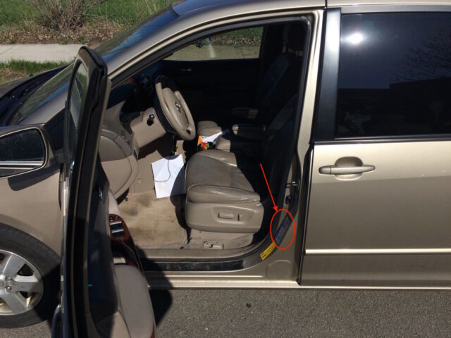
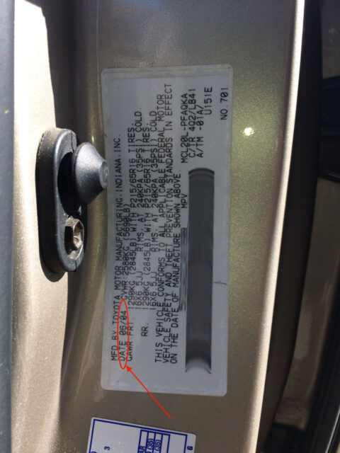
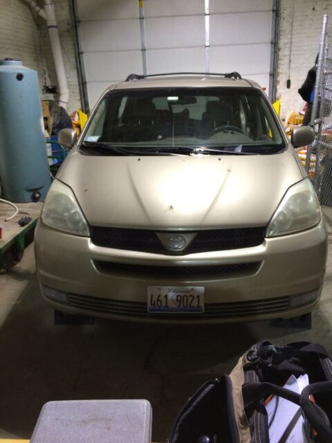
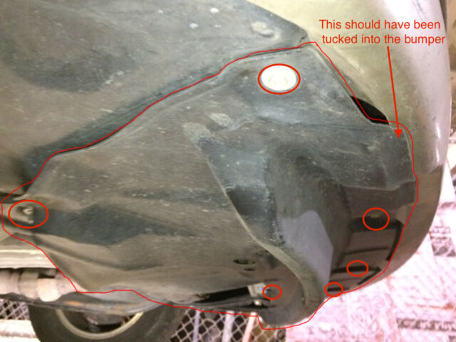
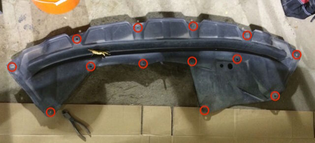
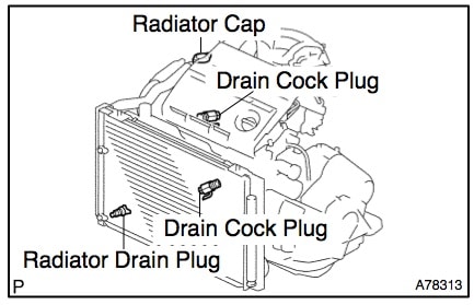
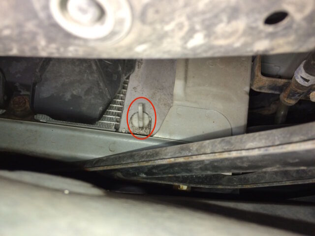
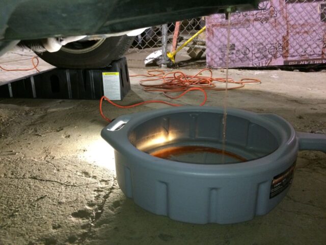
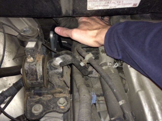
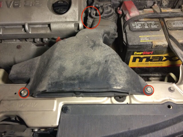
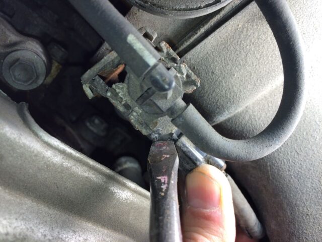
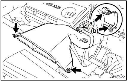
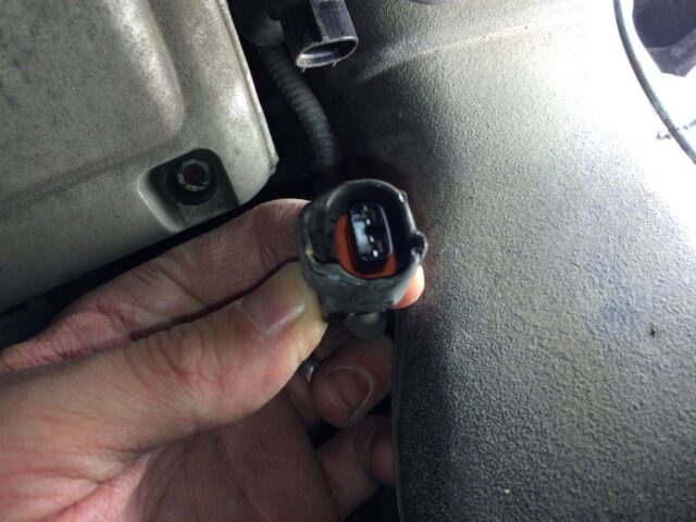
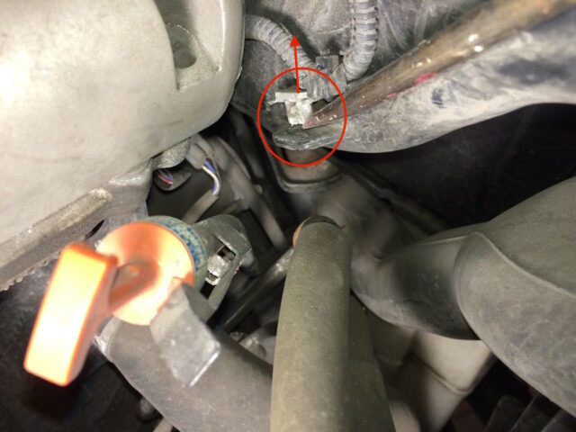
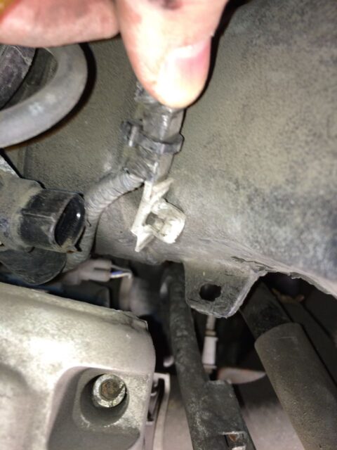
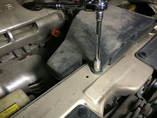

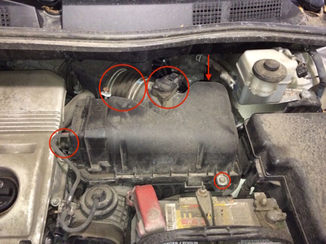
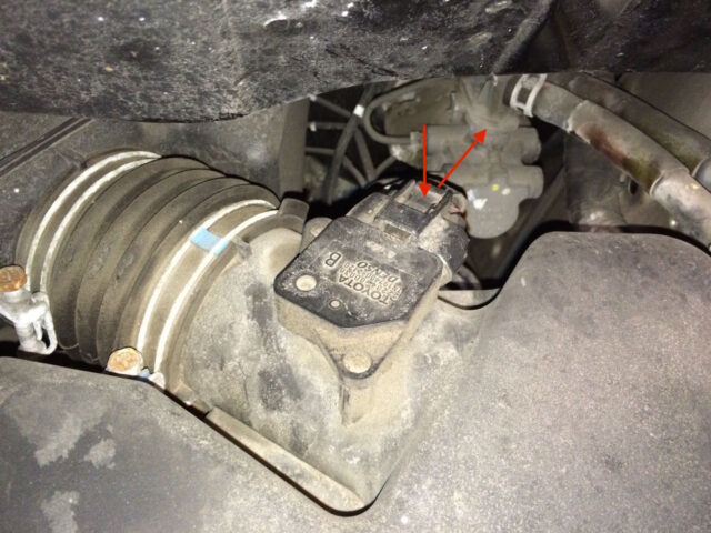
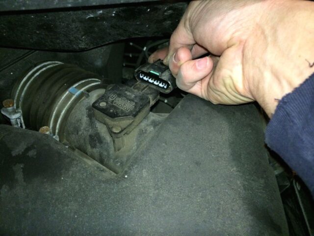
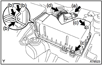
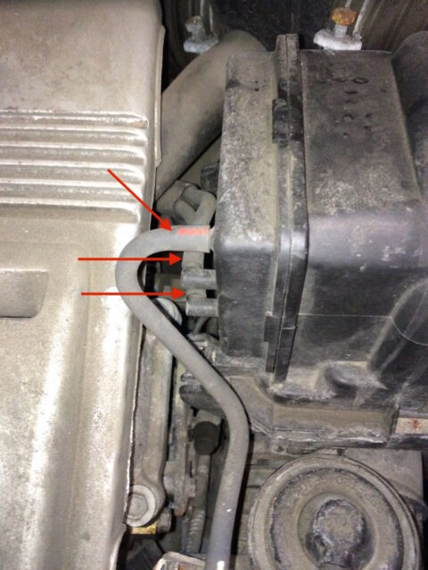
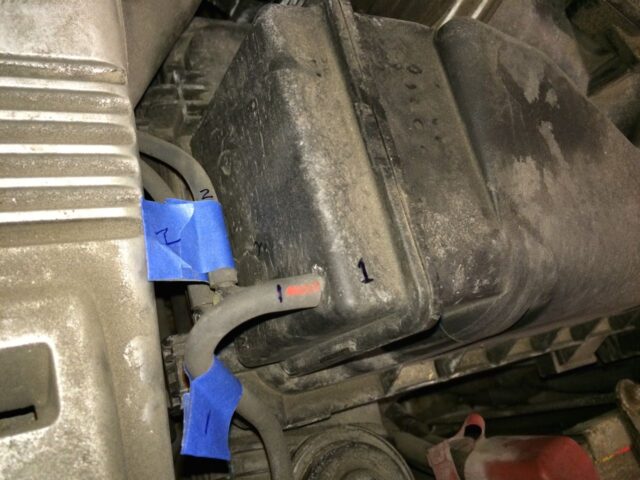
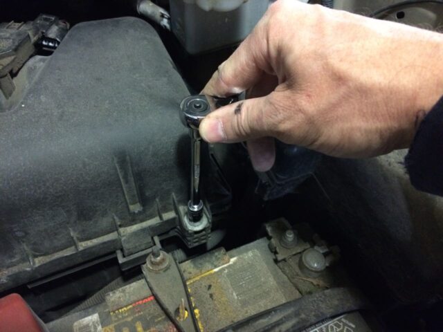
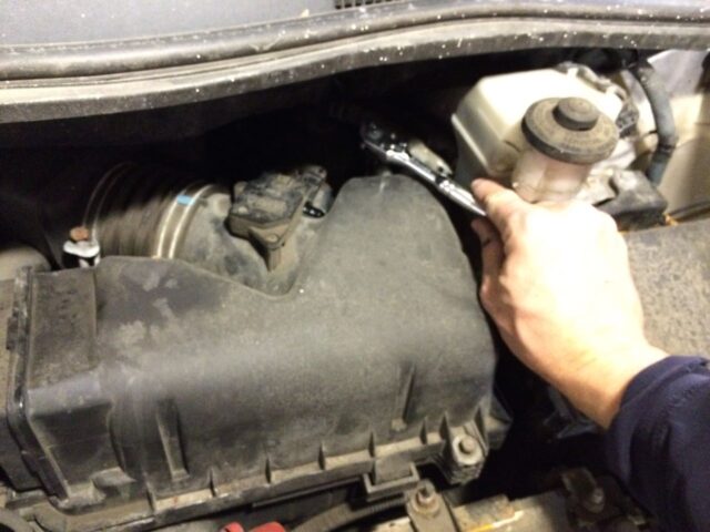
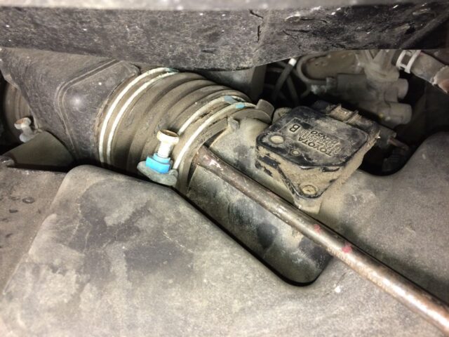
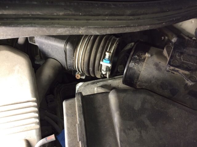
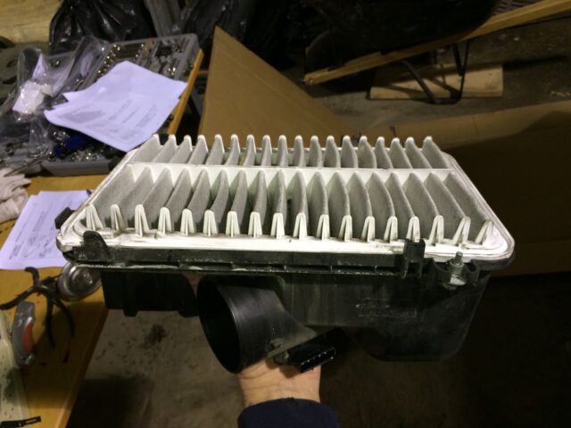
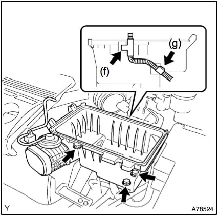
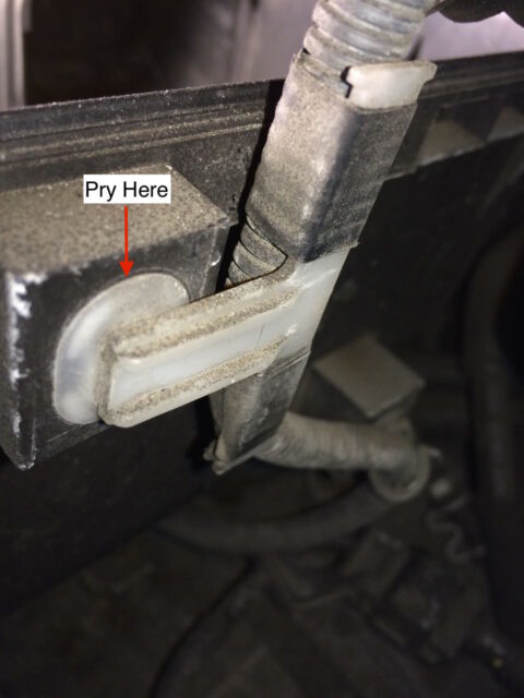
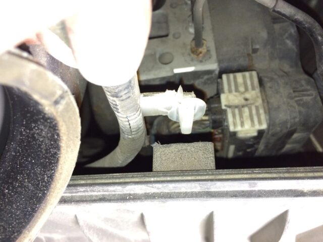
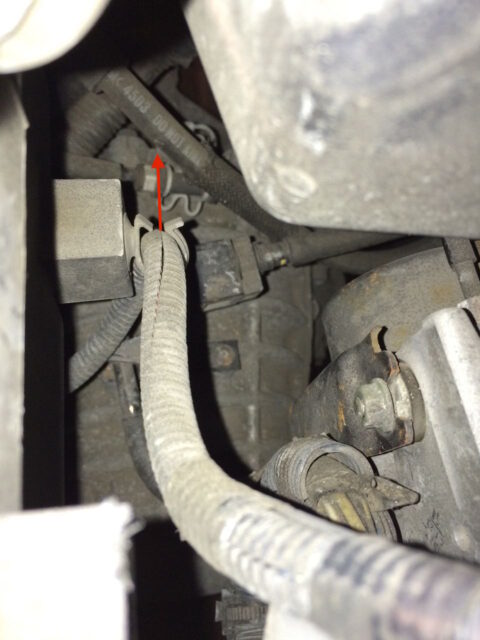
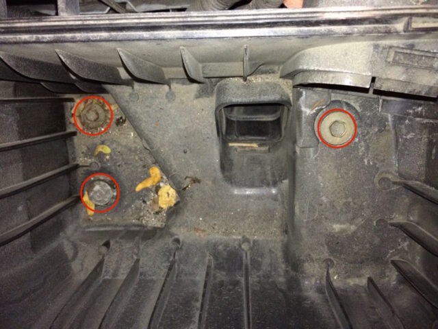
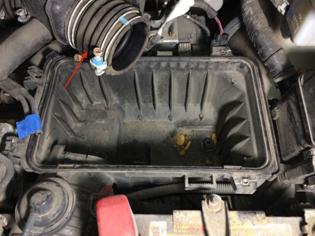
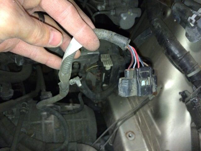
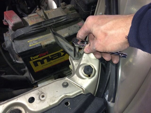
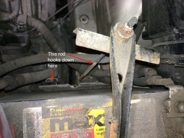
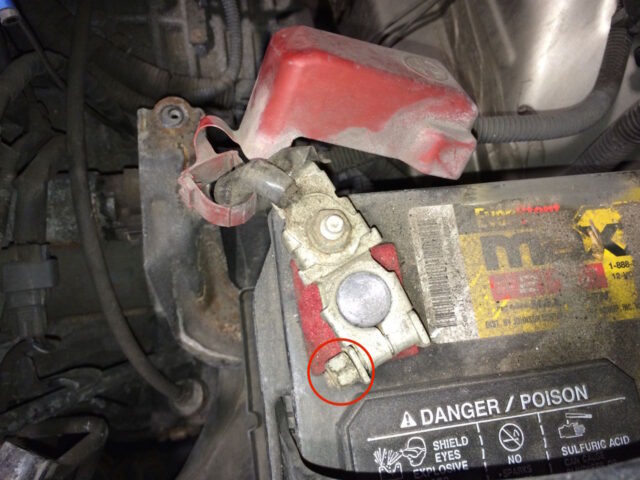
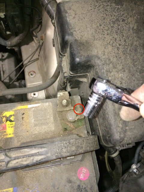
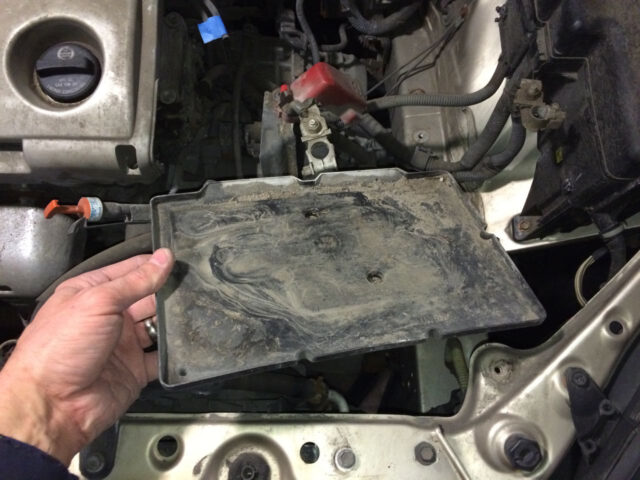
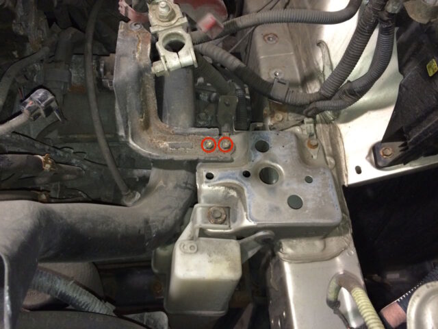
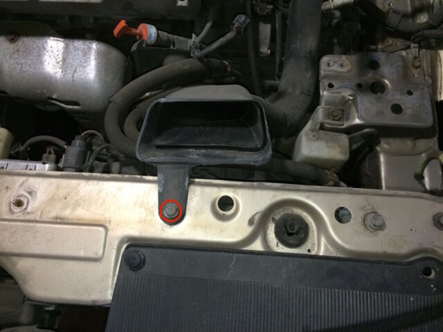
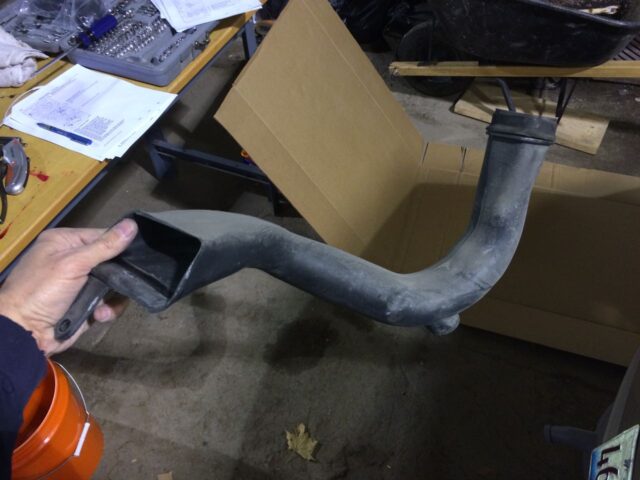
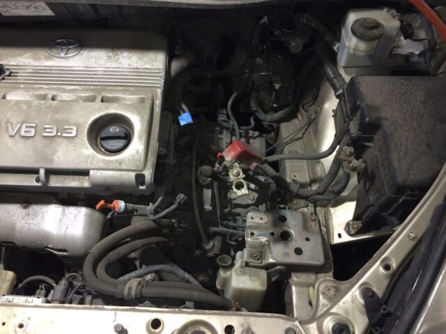
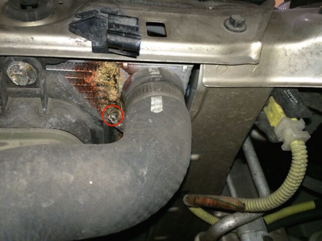
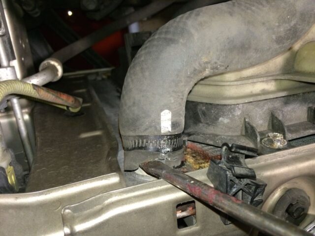
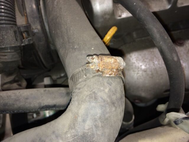
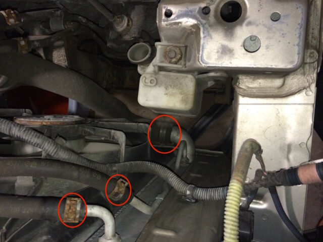
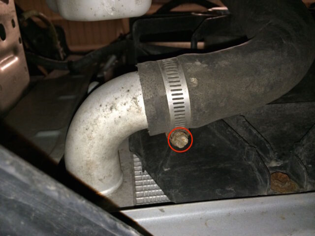
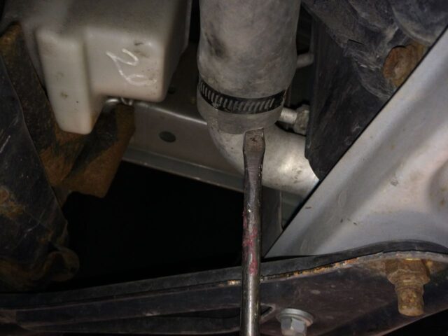
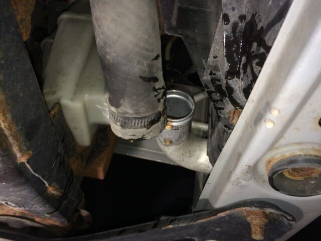
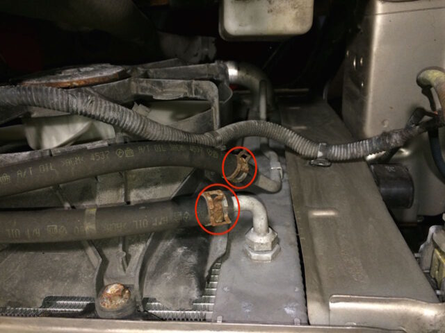
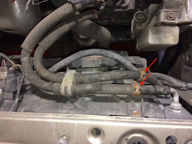
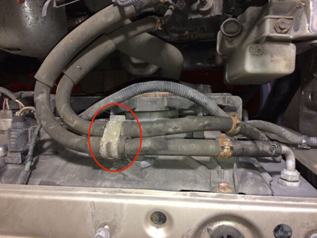
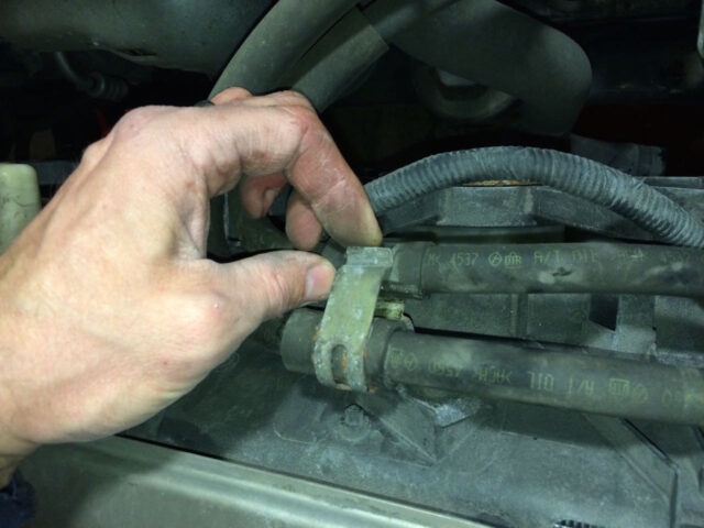
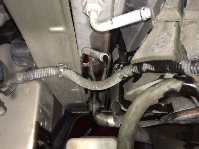
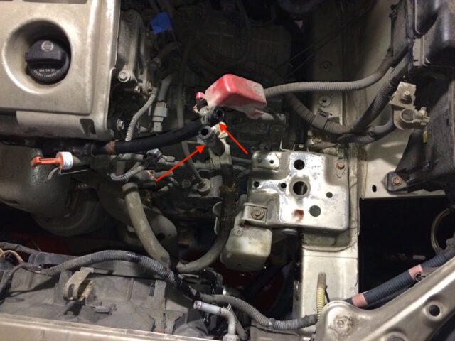
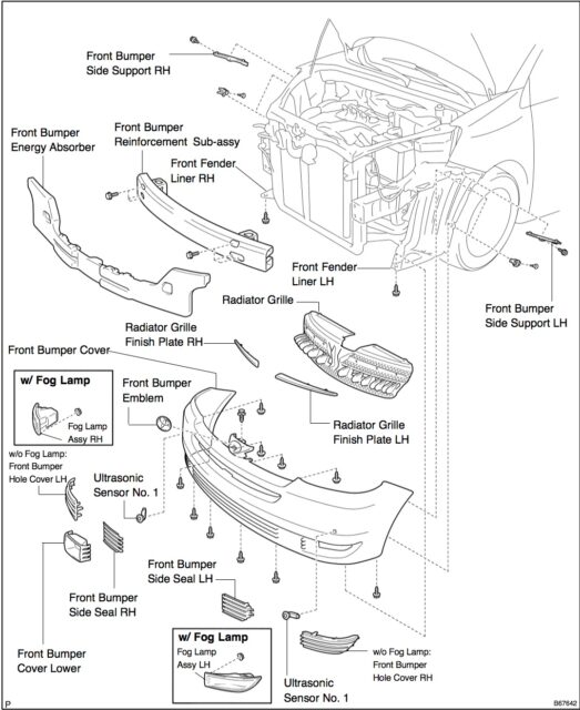
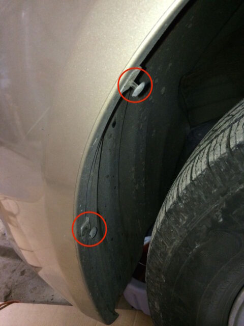
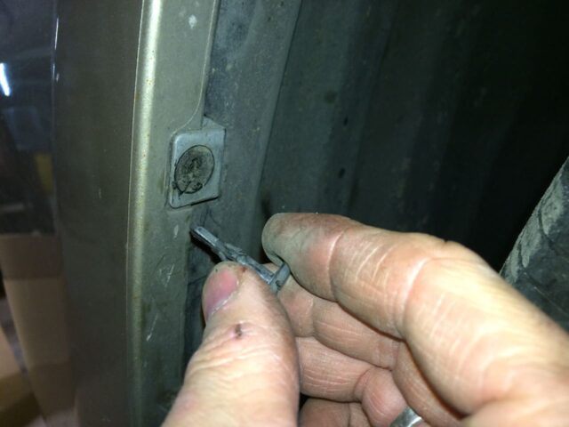
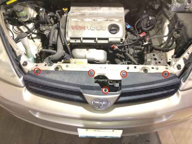
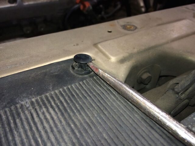
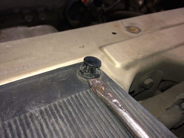
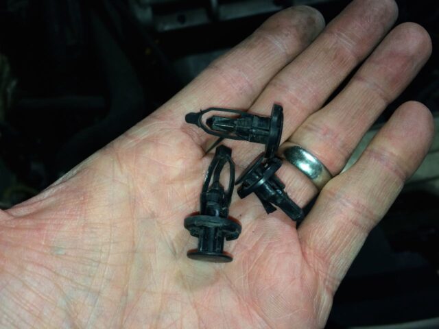
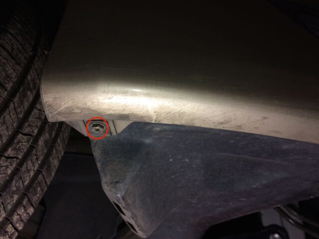
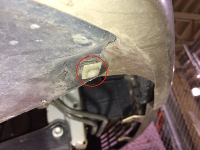
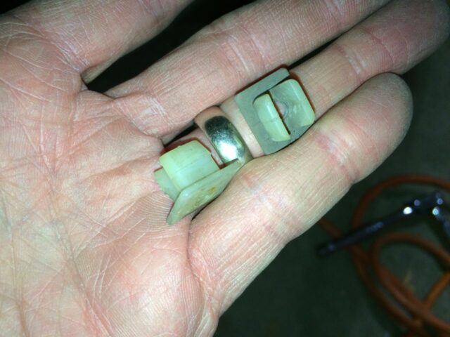
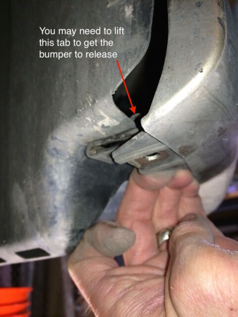
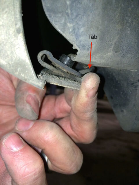
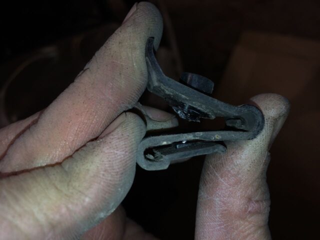
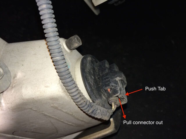
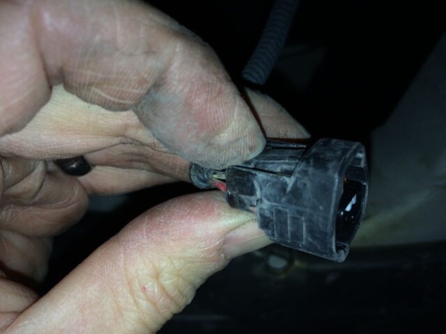
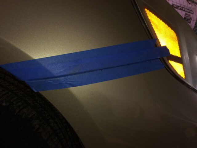
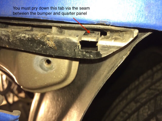
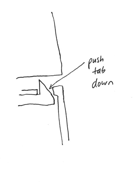
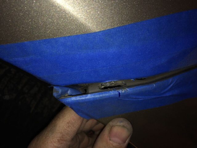
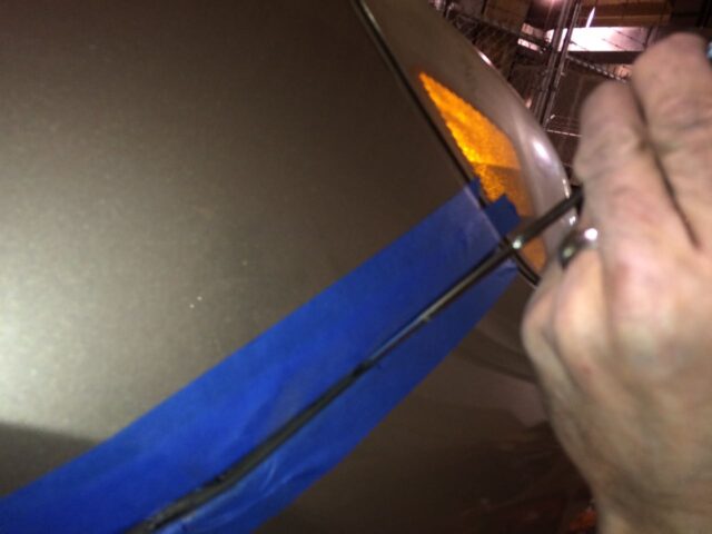
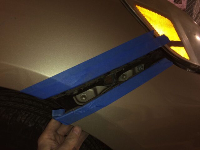
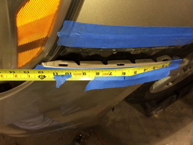
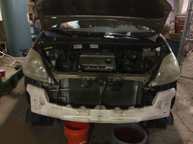
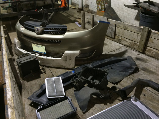
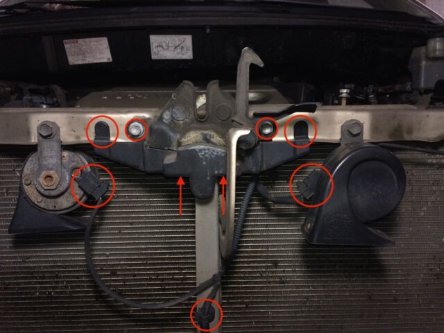
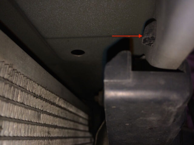
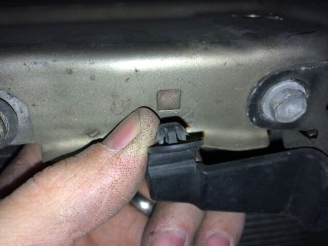
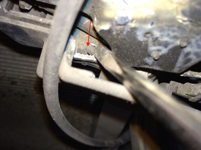
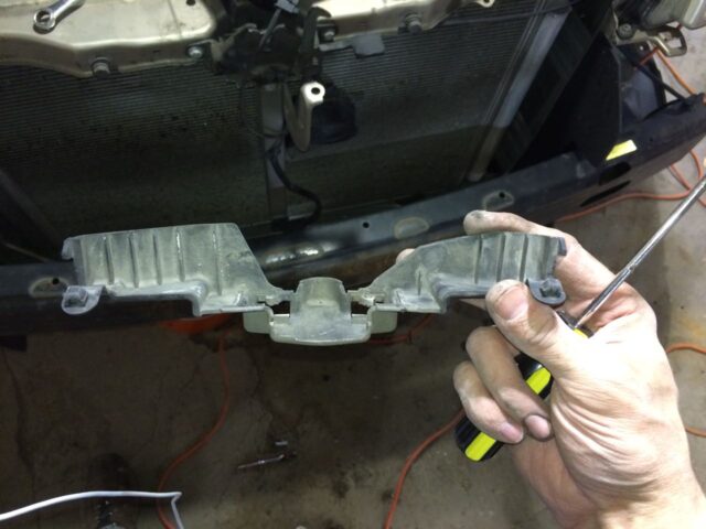
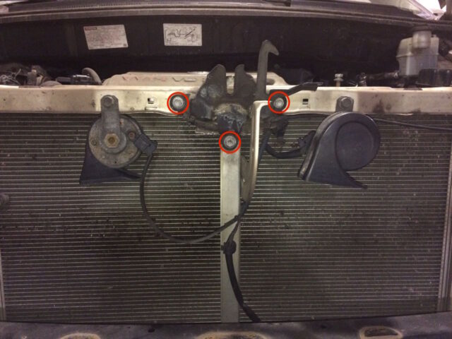
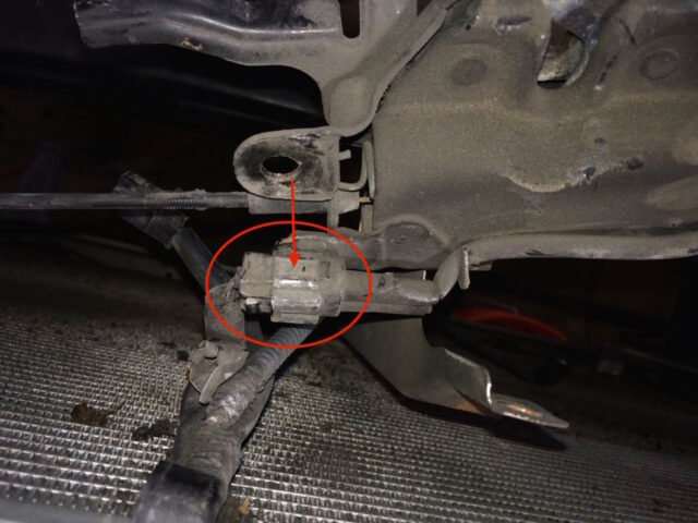
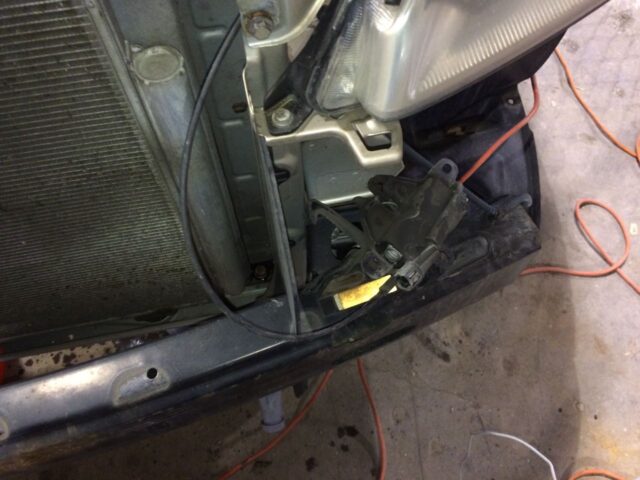
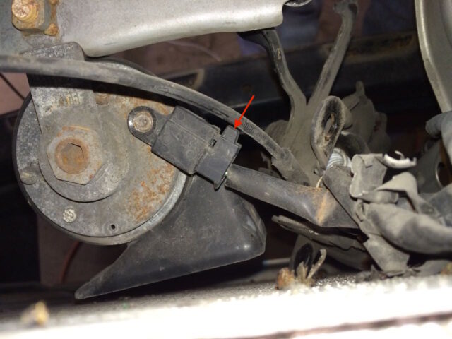
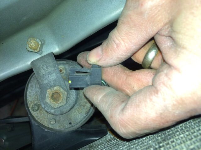
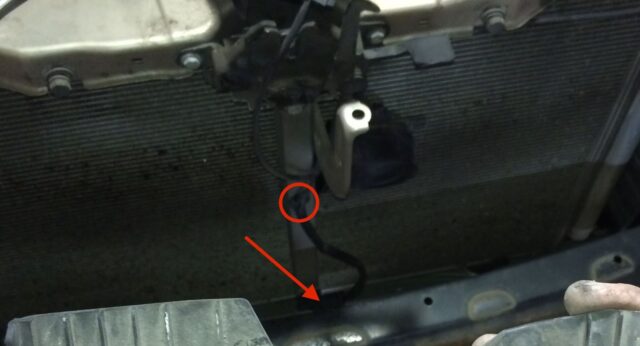

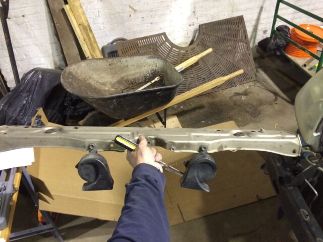
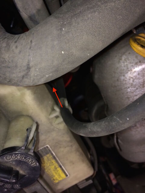
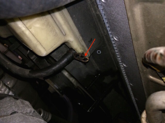
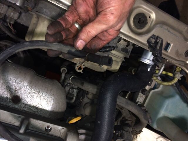
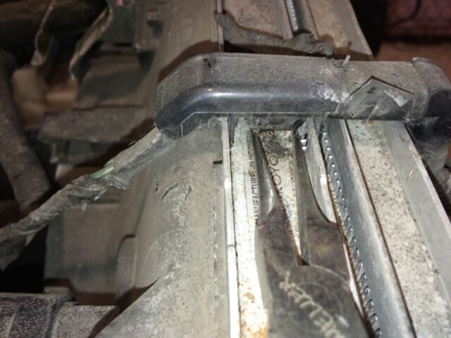
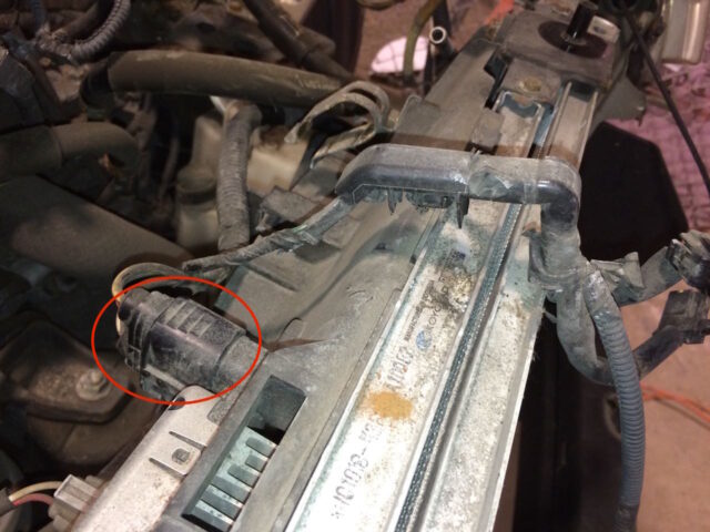
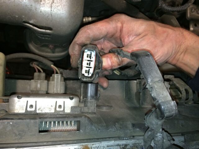
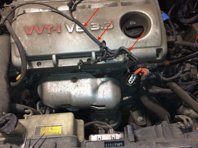
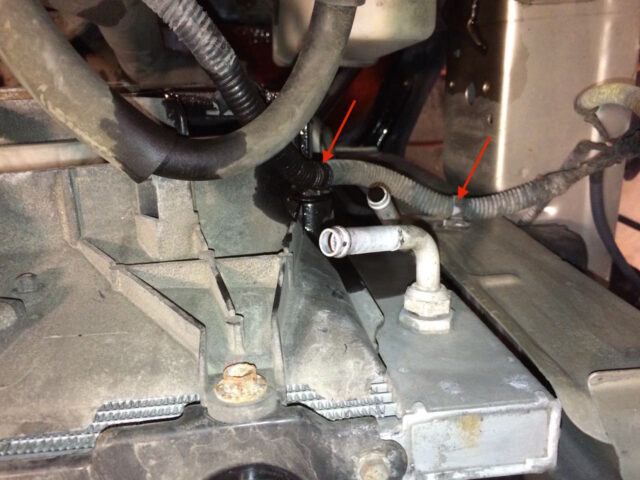
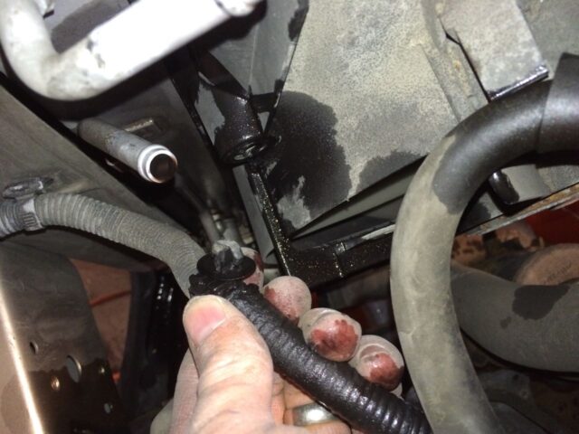
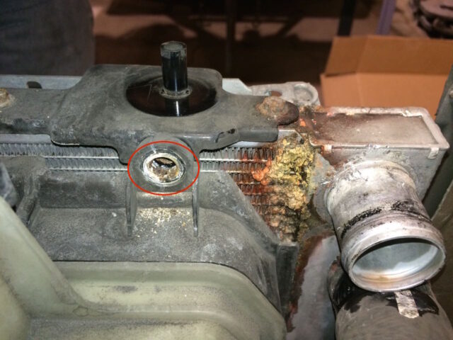
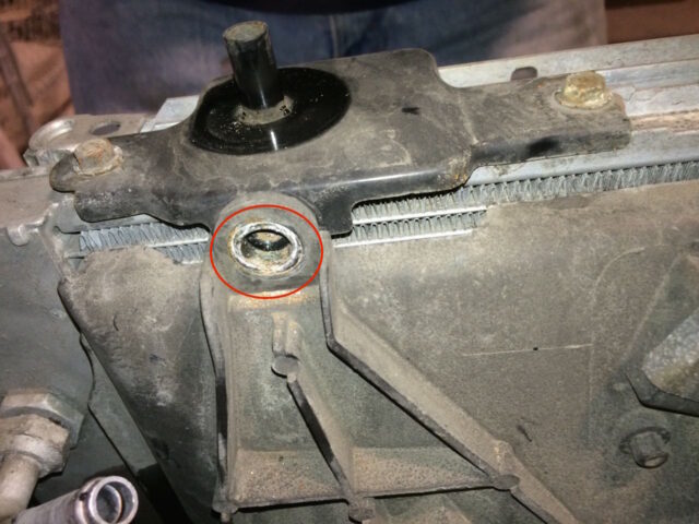
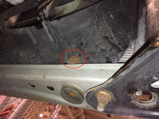
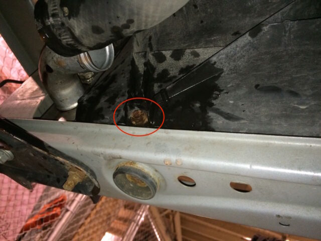
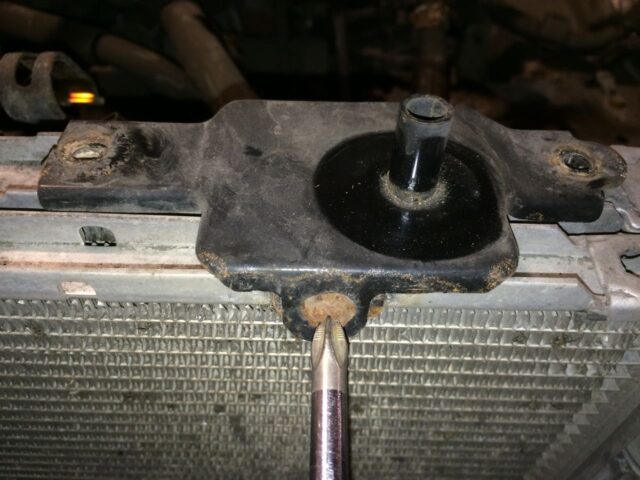
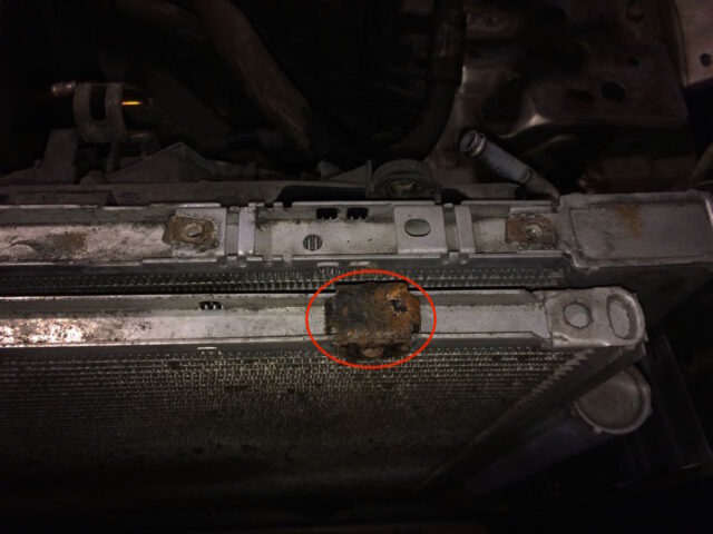
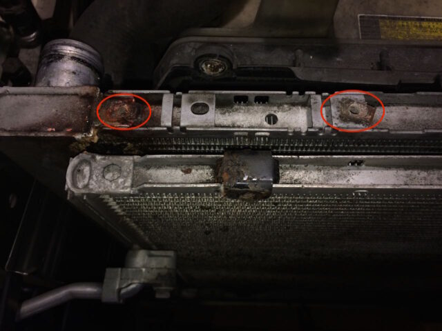
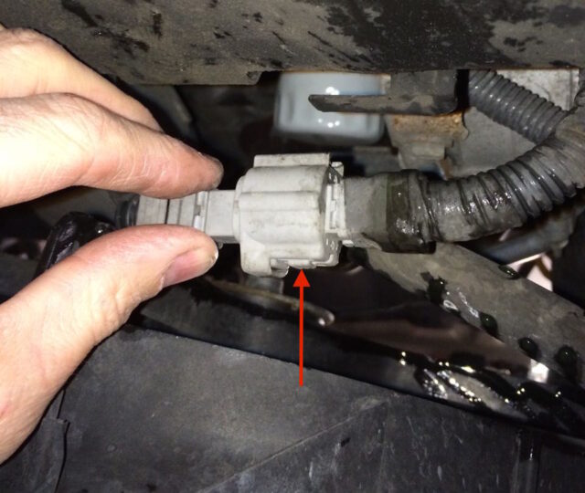
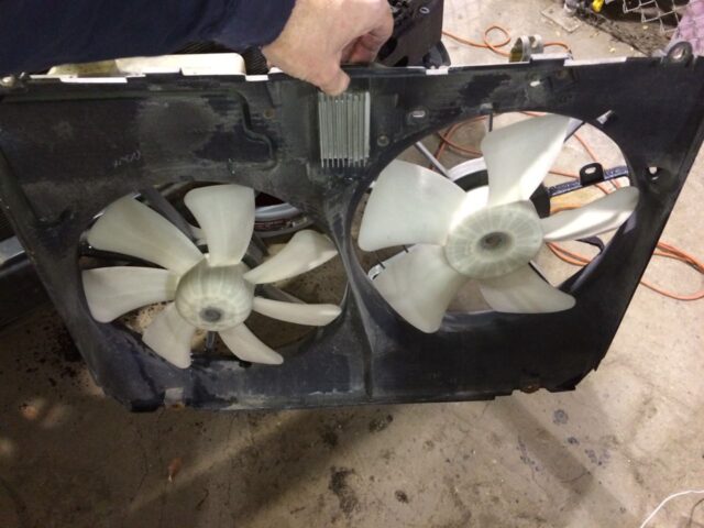
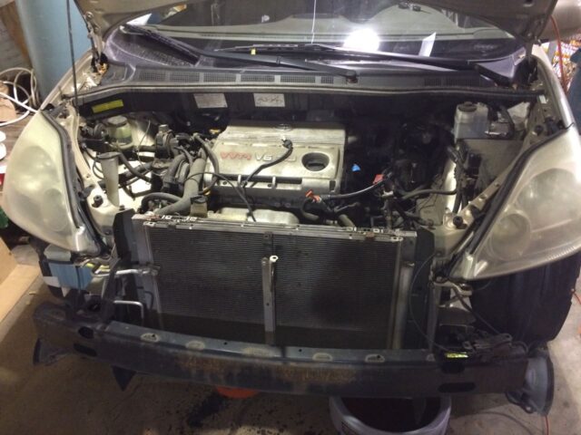
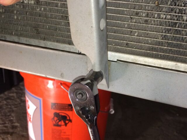
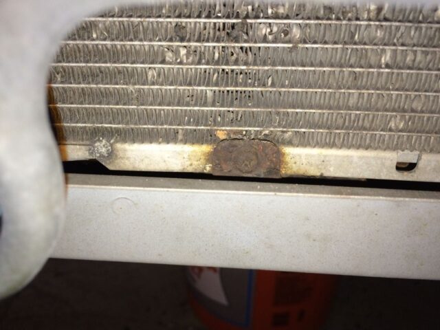
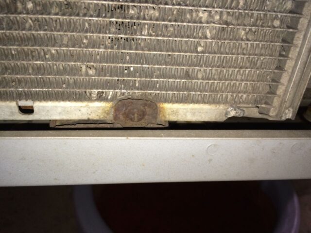
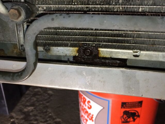
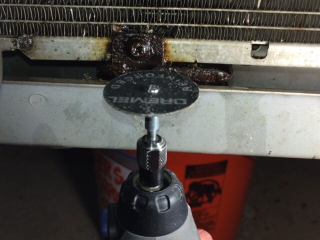
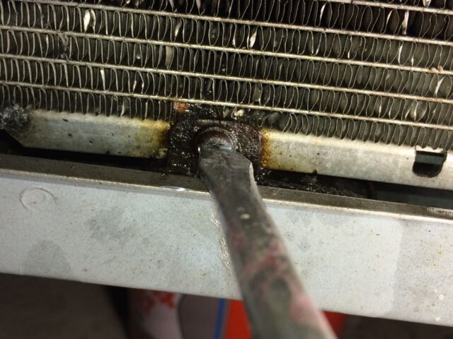
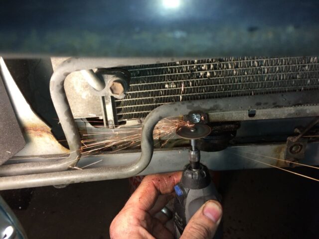
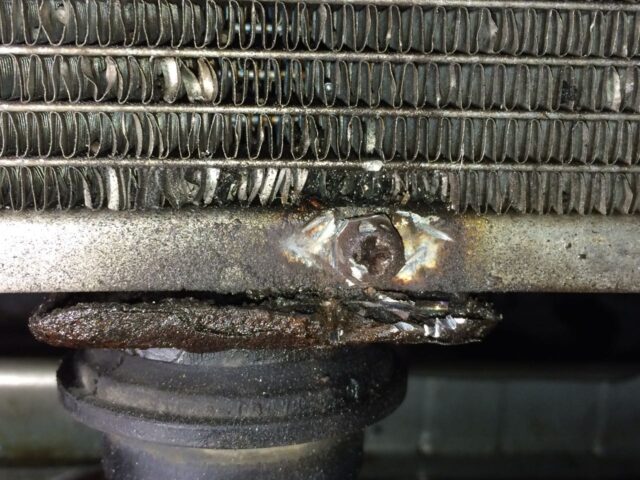
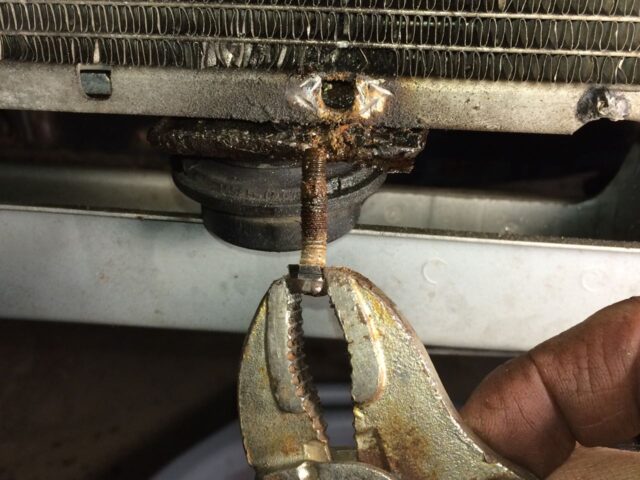
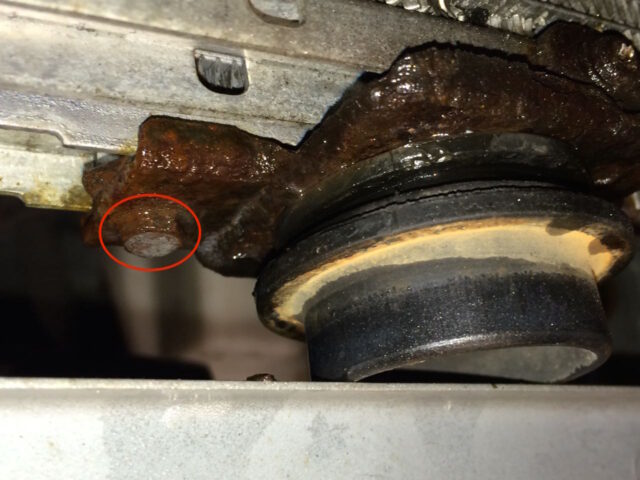
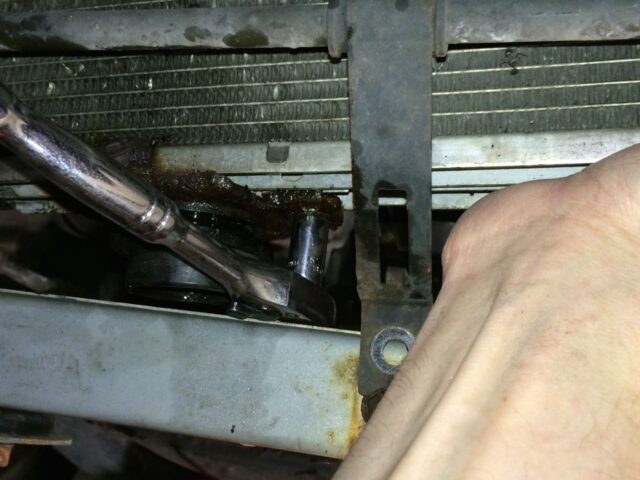
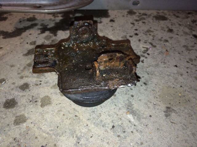
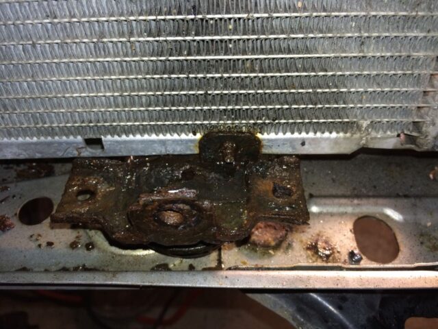
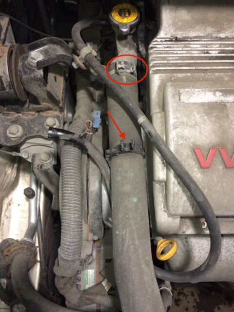
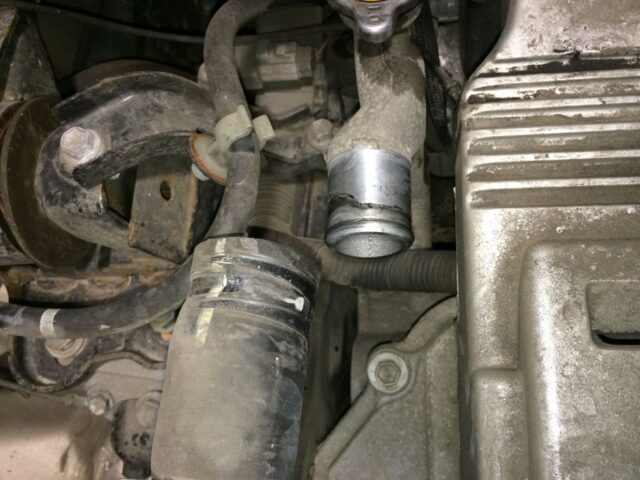
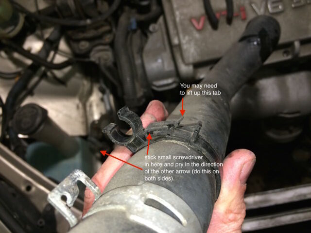
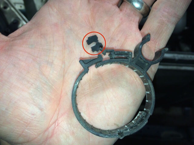
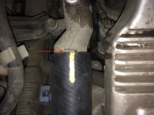
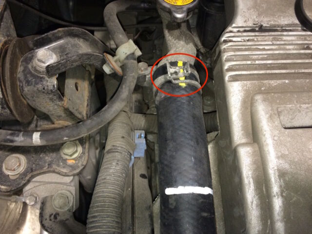
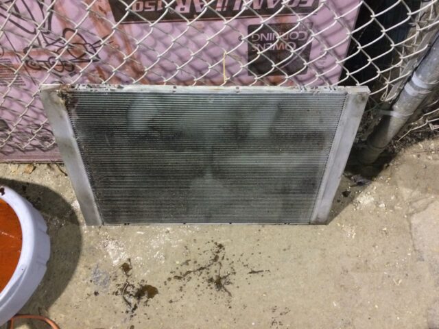
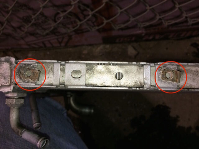
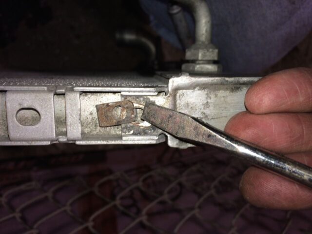
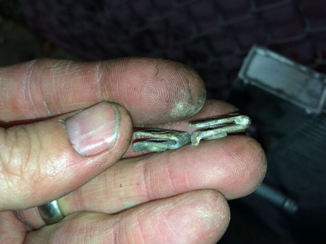
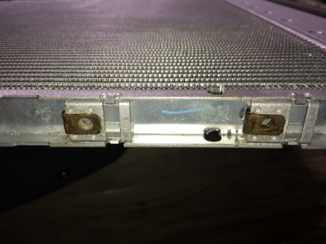
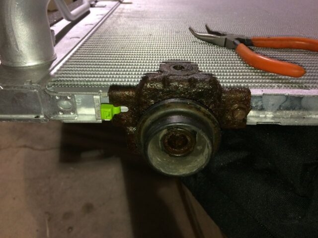
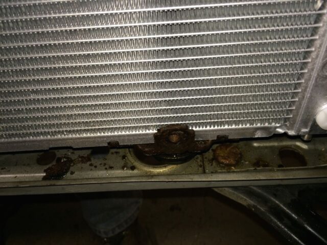
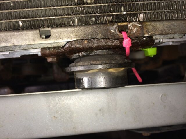
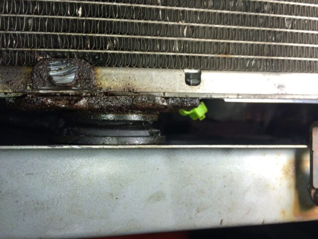
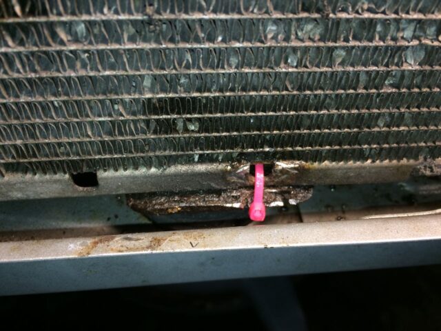
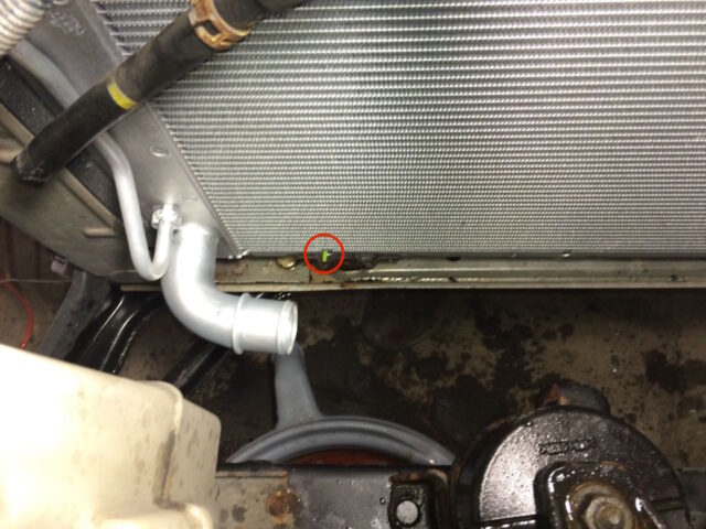
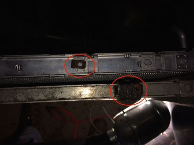
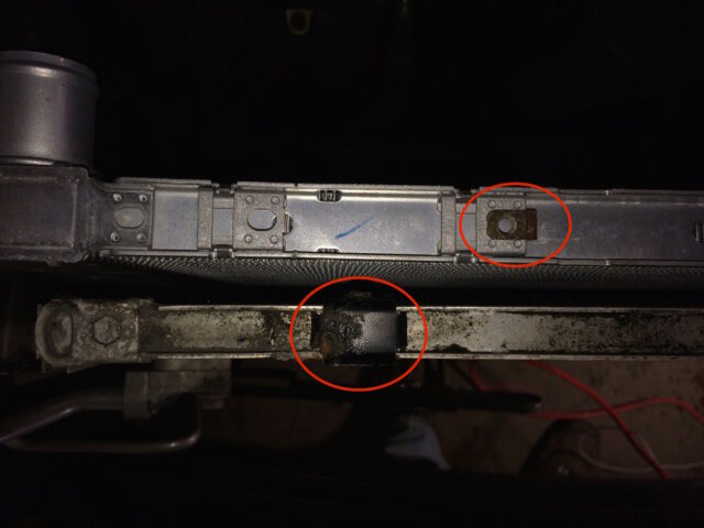
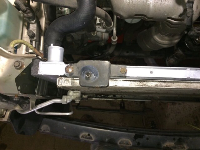
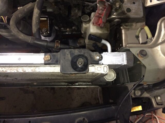
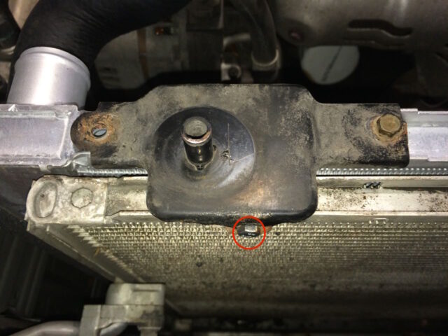
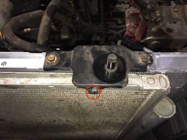
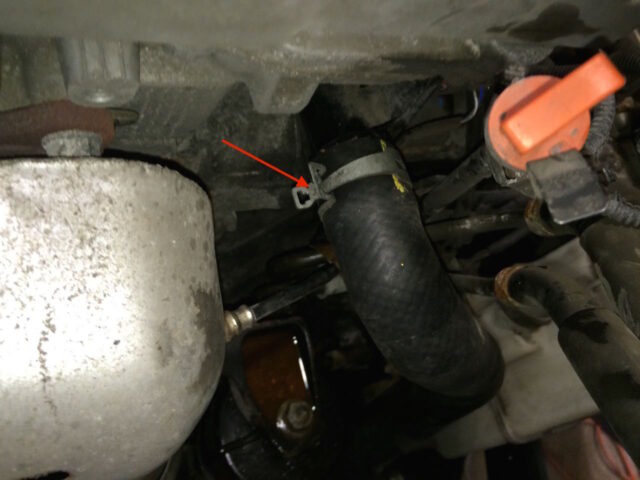
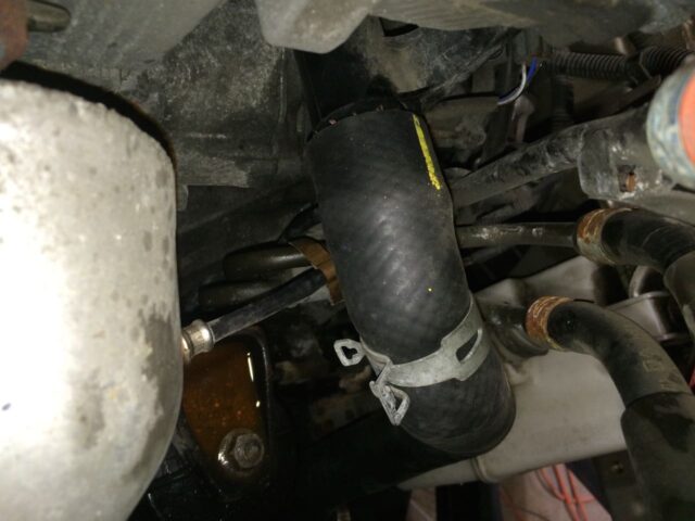
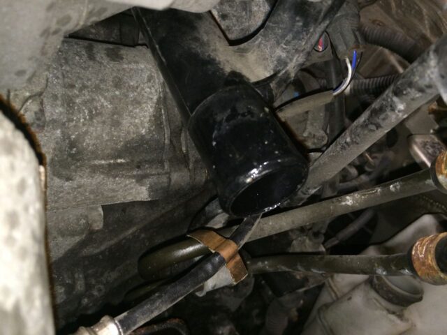
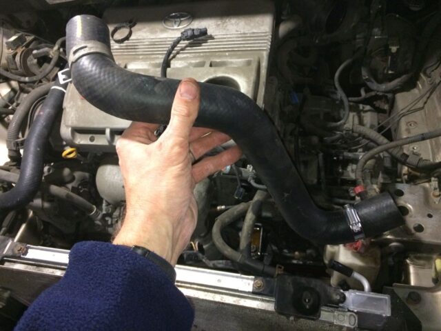
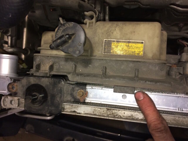
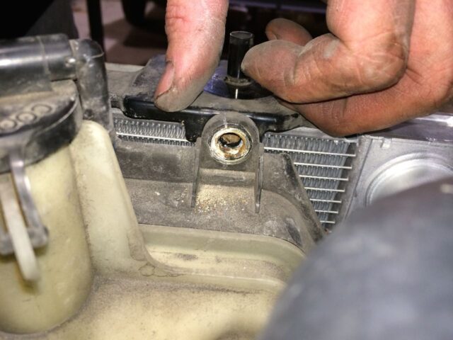
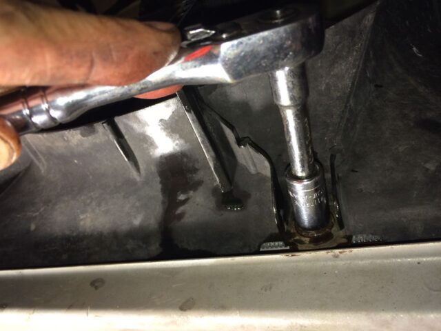
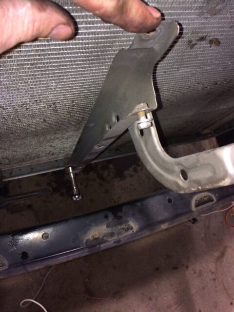
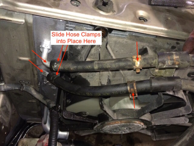
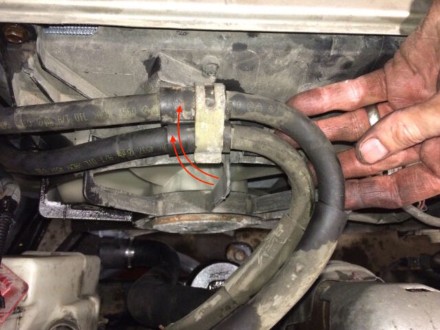
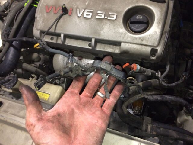
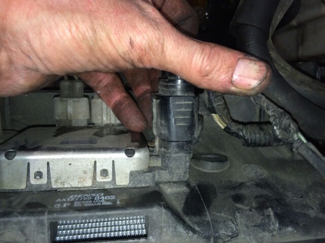
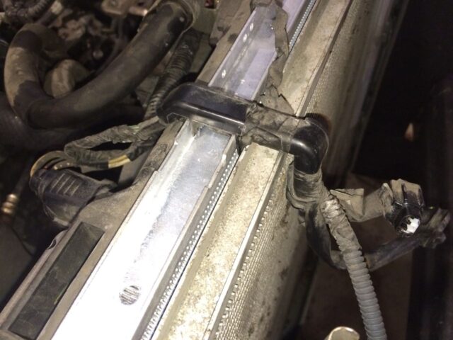
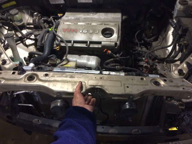
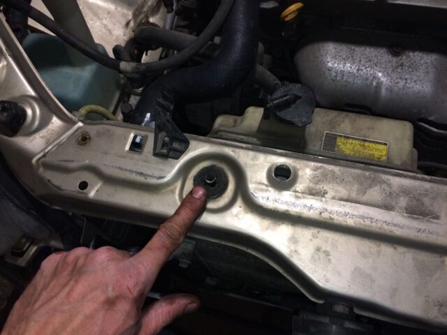
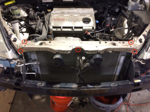
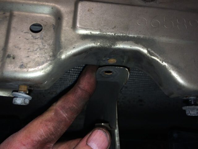
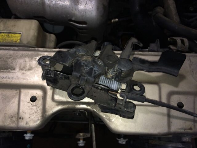
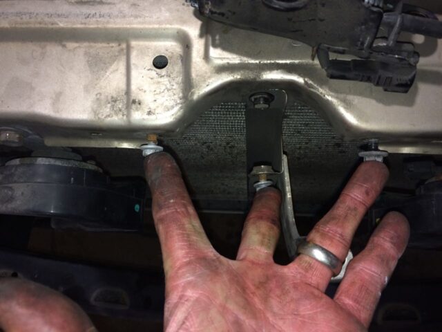
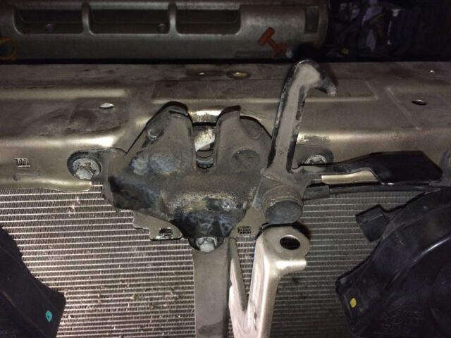
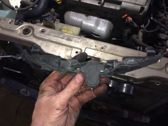
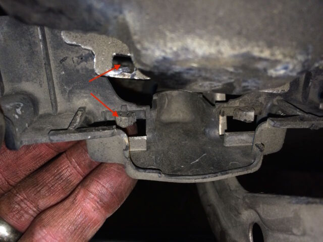
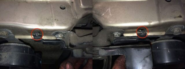
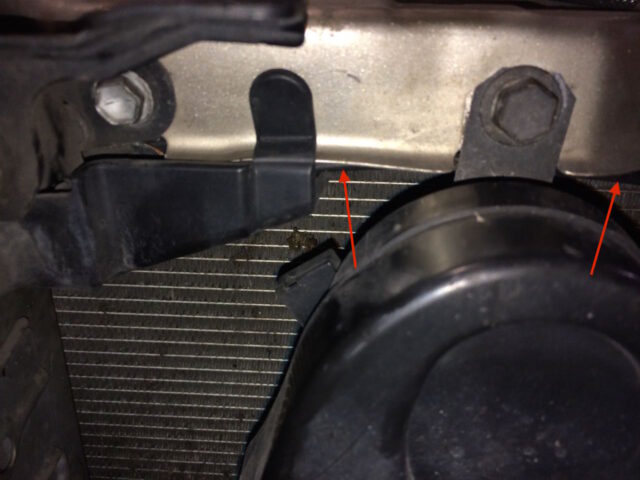
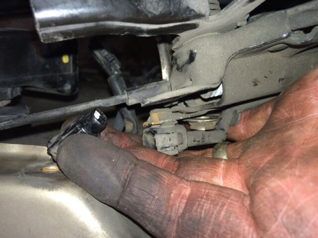
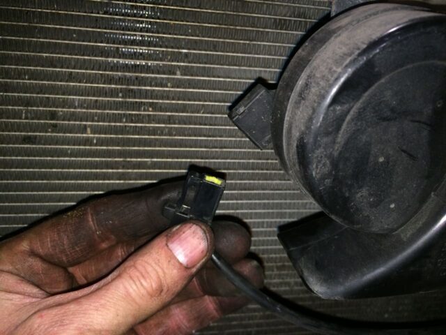
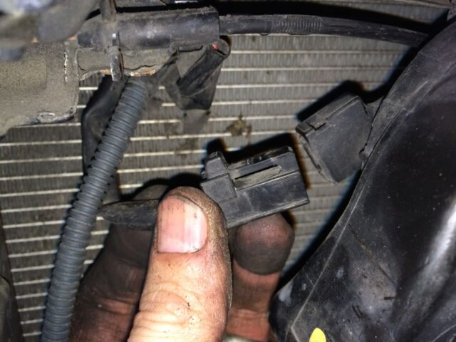
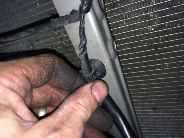
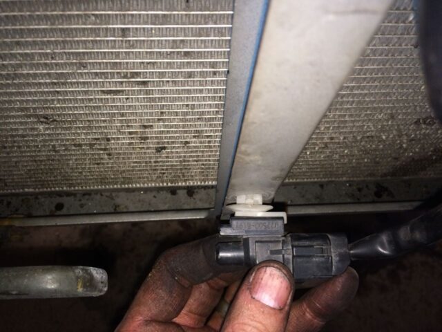

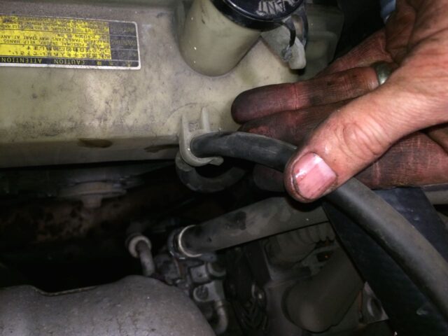
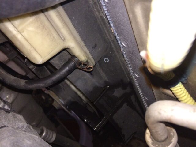
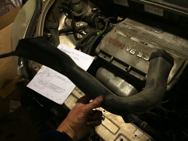
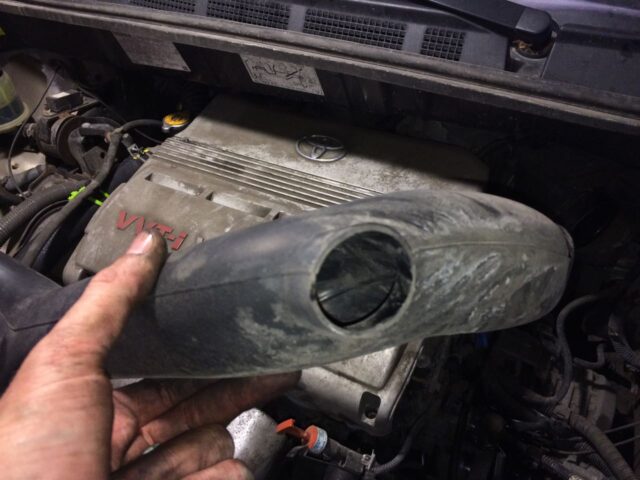
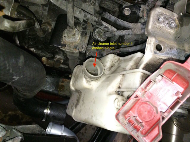
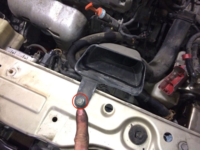
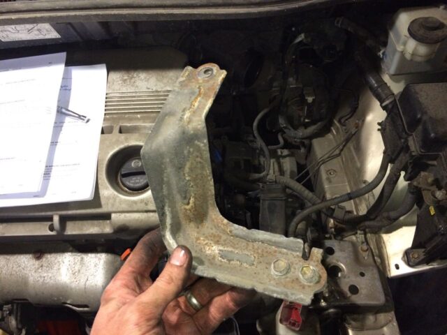
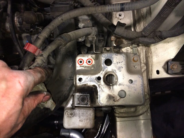
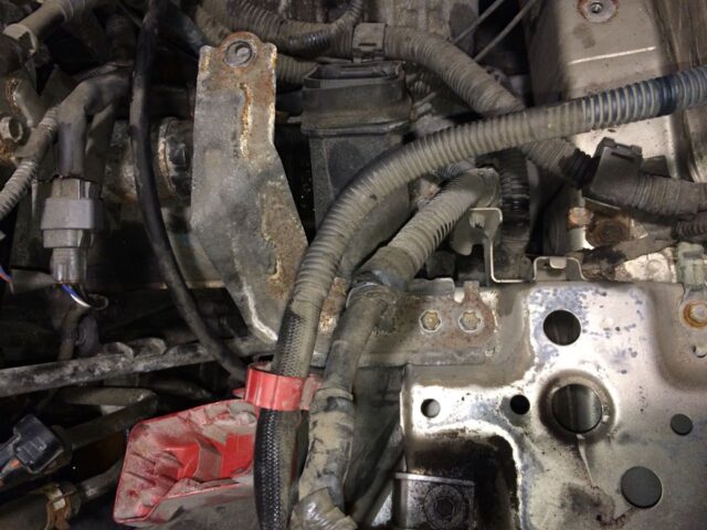
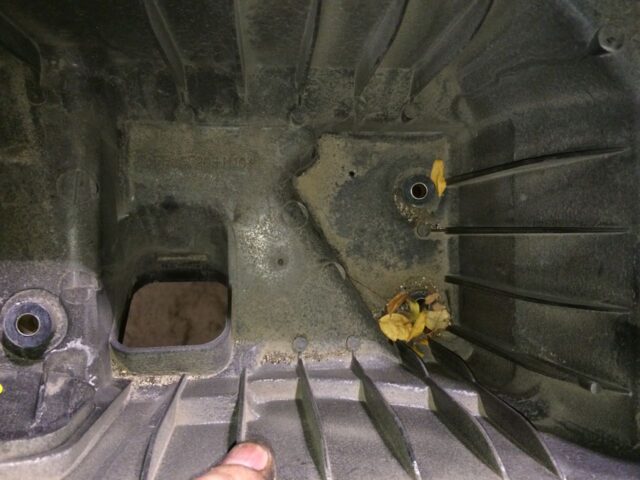
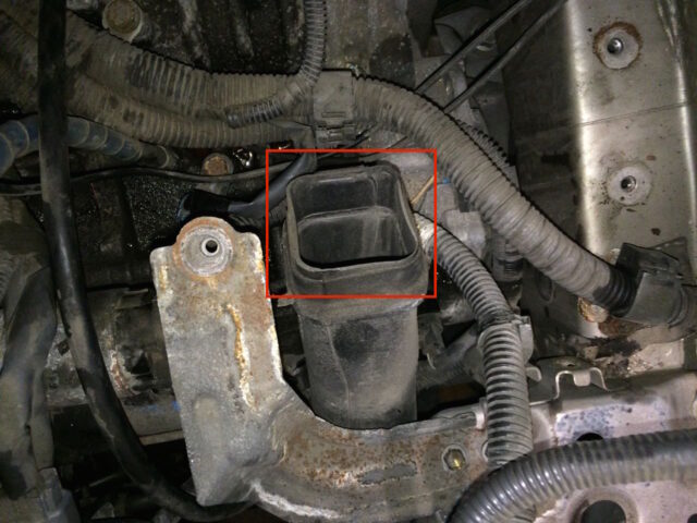
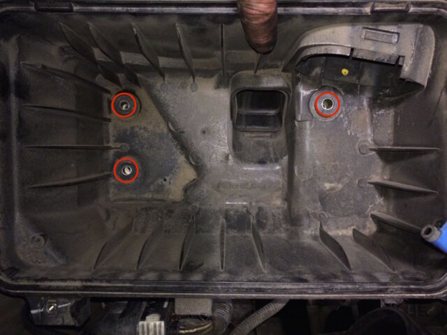
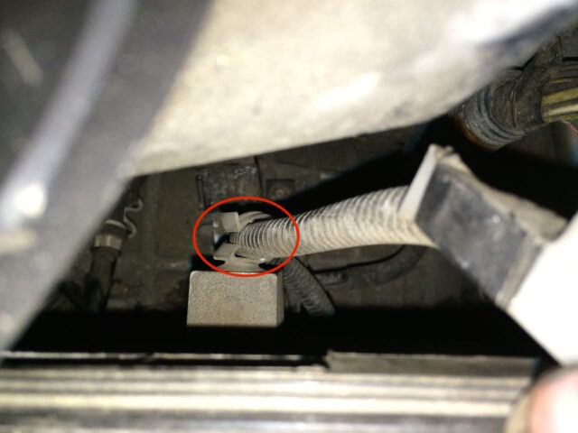
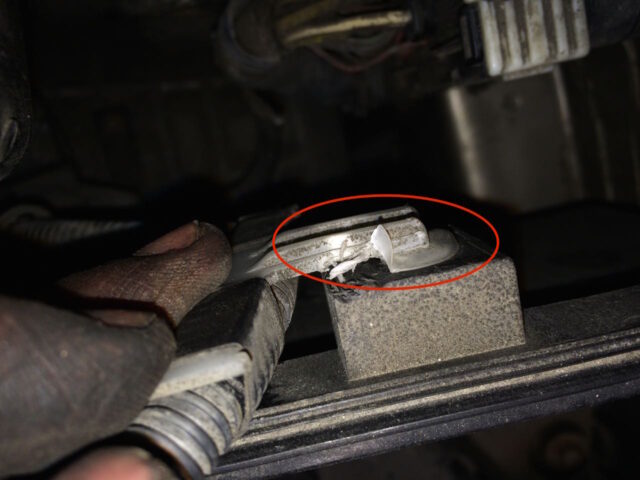
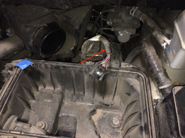
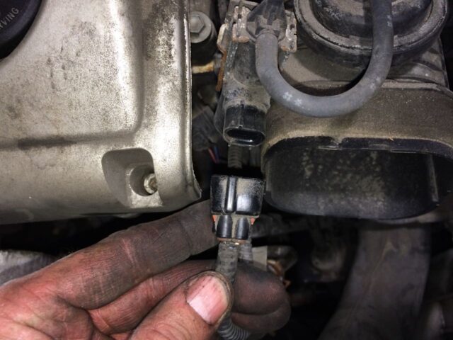
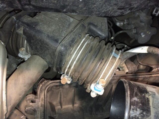
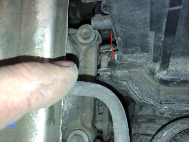
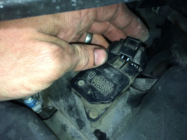
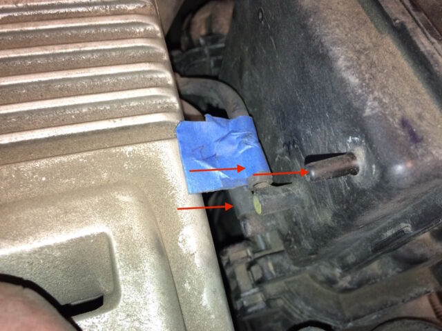
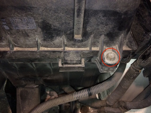
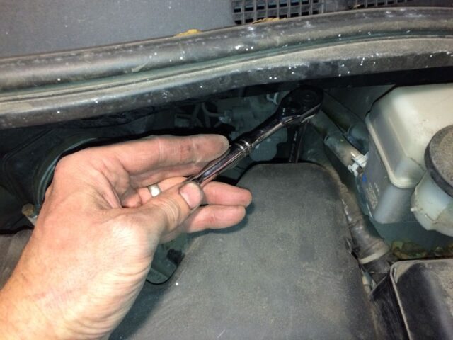
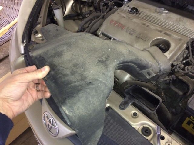
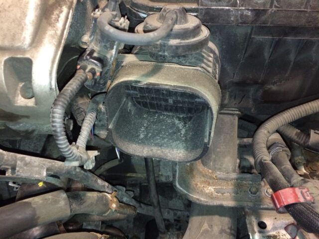
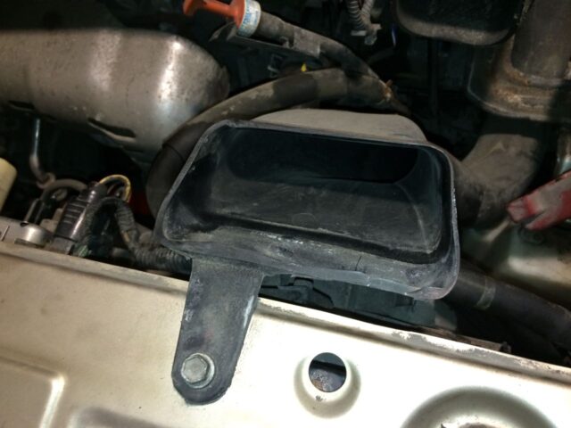
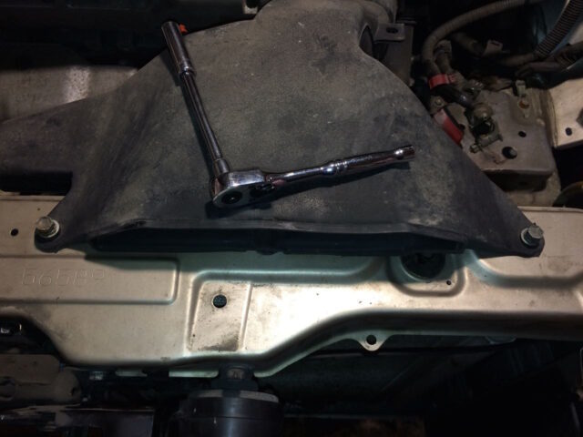
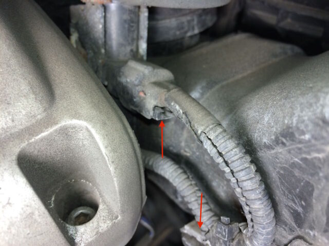
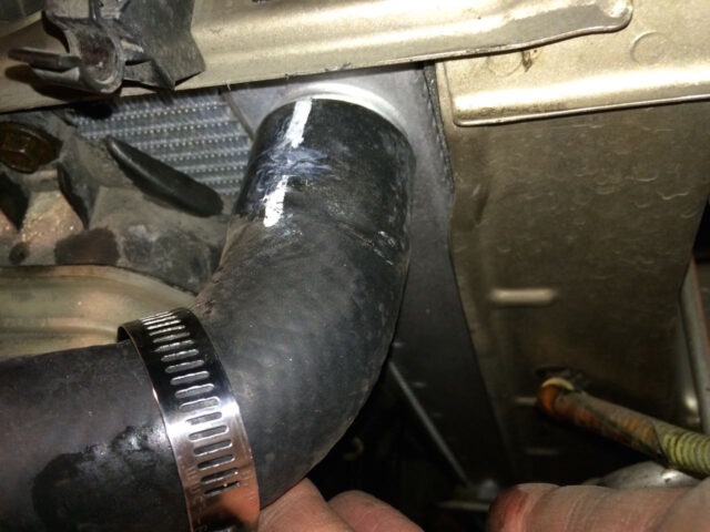
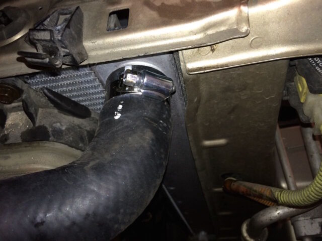
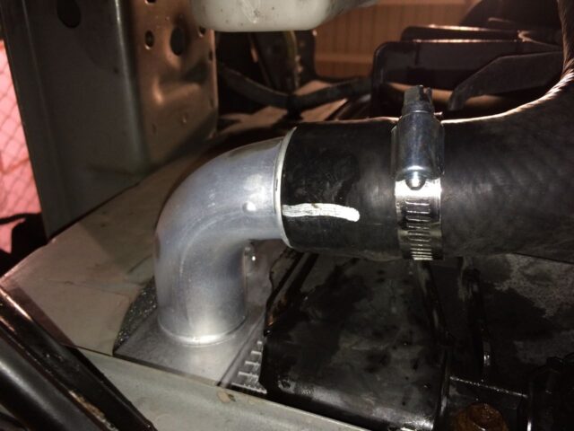
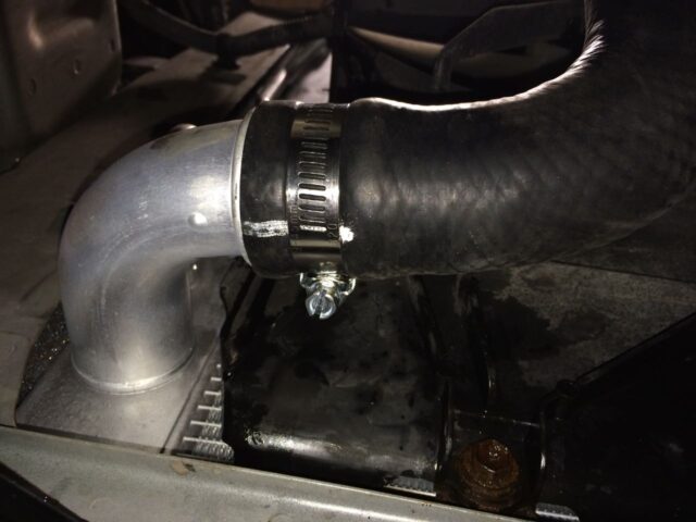
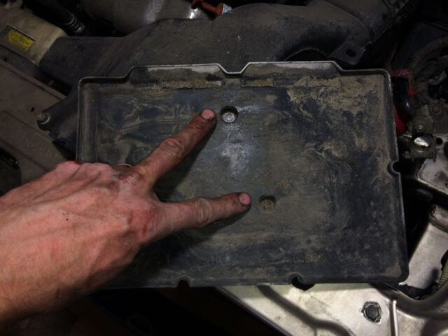
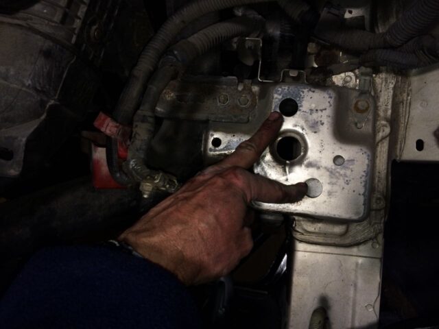
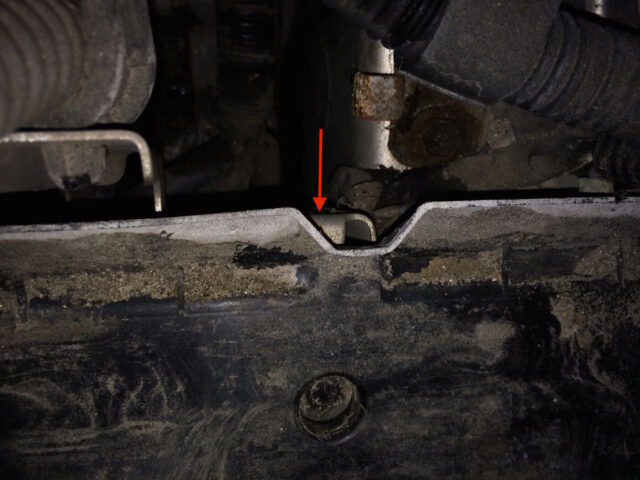
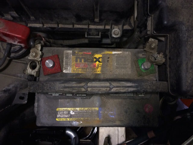
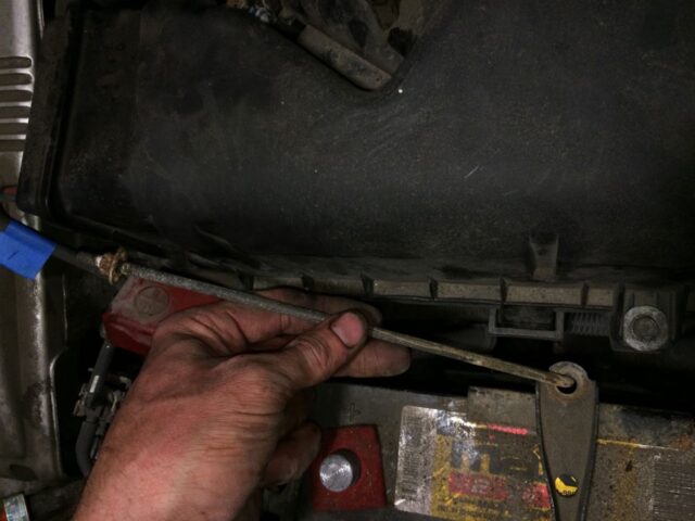
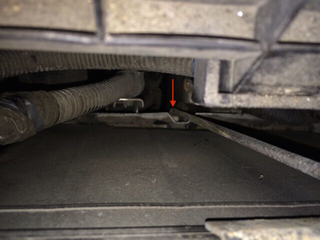
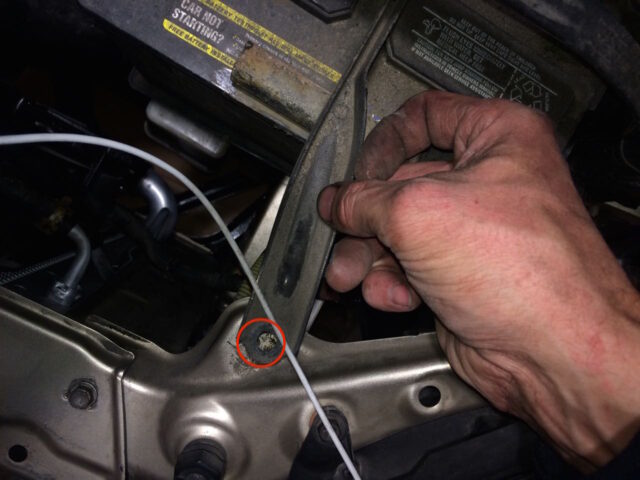
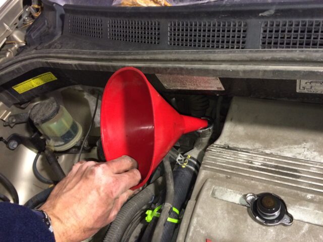
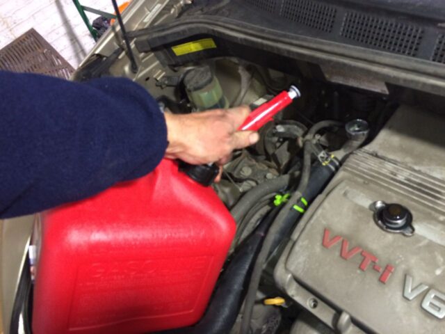
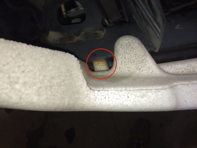
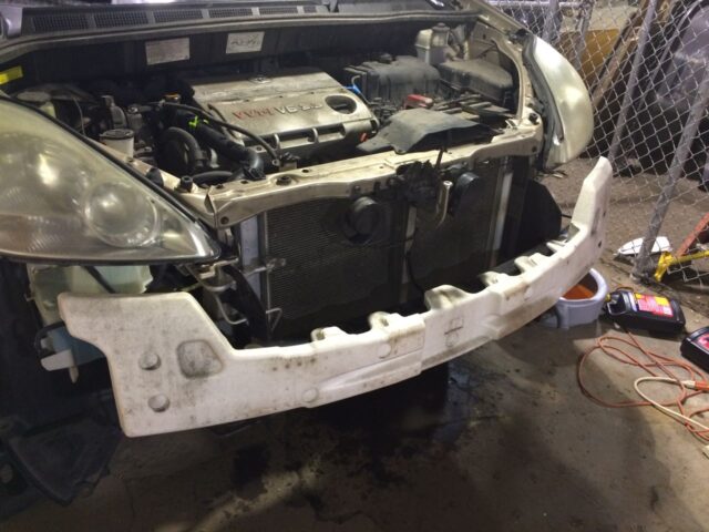
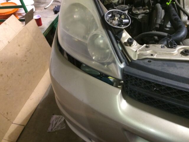
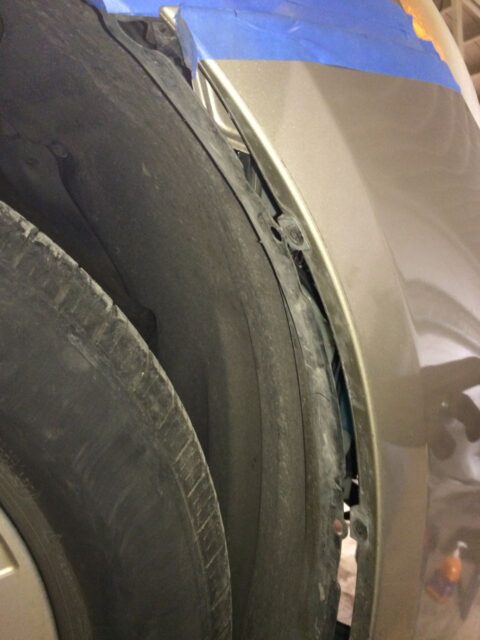
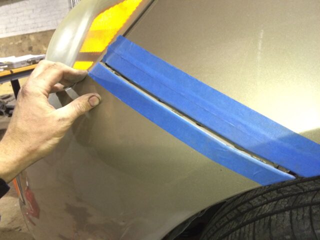
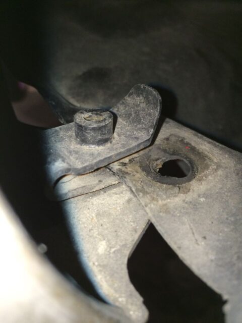
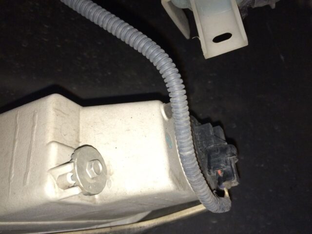
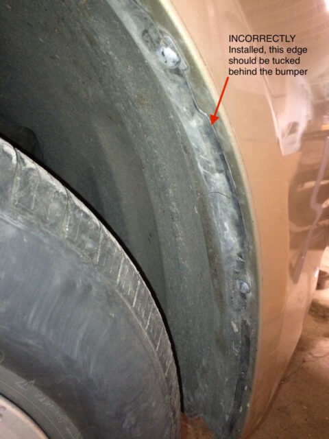
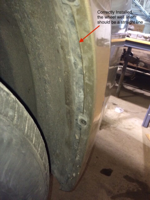
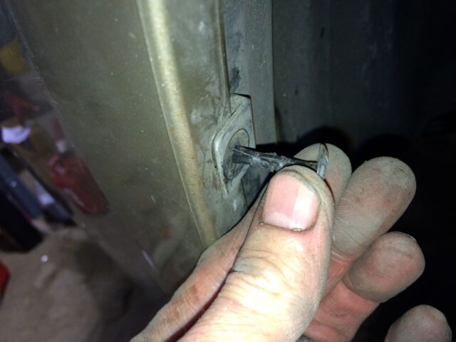
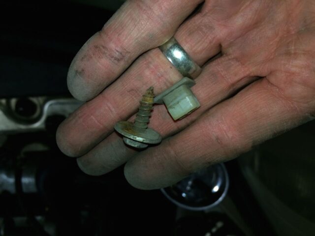
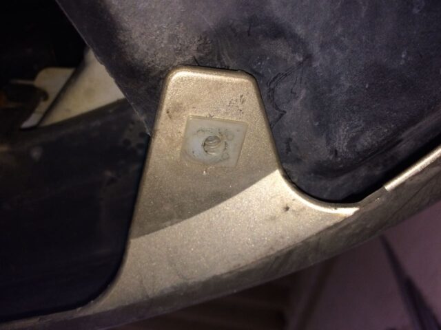
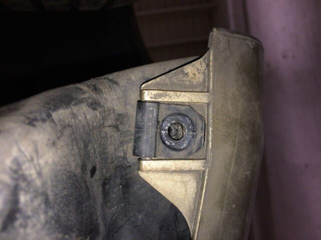
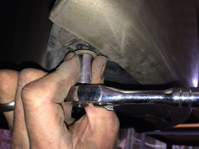
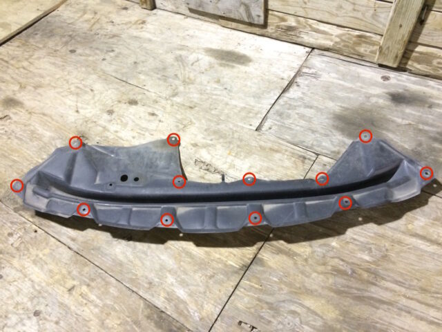
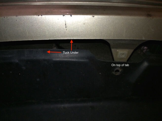
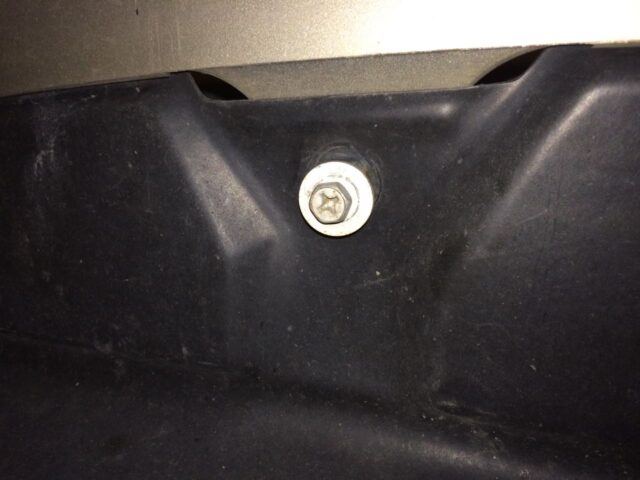
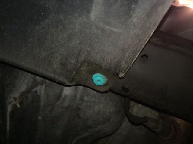
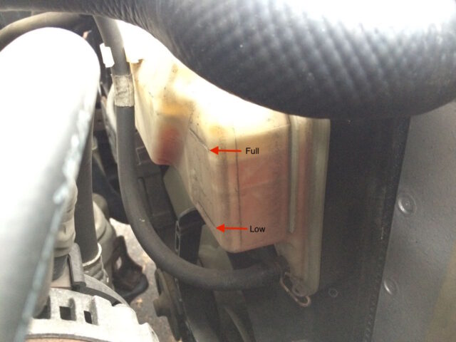
Great set of directions, with a few differences from my 2007 Sienna. Between your photos and AllData DIY, I was able to change the radiator and thermostat over four days.
Good job Roman–the radiator replacement on these Sienna’s is quite the job!!
John, thank you very much for sharing your effort in such great detail. This was a major help in replacing the radiator on my 2008 Sienna – 186K miles and going!
Thank you so much for this in-depth analysis!
Thank you for this detailed guide! I used your guide to fix my sliding door earlier this year so I was glad to find this one for the radiator. I have a 2009 Sienna with 169,000 miles and it blew the transmission cooler line out where it attaches to the radiator. Luckily it happened when I was in my driveway just after getting home with my kids from an appointment an hour away. On the 2009 Sienna a few things are different which actually made it easier so I could skip some steps. The thermostat is on the passenger side so I didn’t have to remove the battery or other things on the driver’s side. The thermostat was easy to change by simply removing an idler pully under it and putting a long wrench on the tensioner under that and clamping it until the idler pully was put back on. Also – all I had to do on the bottom of the radiator was take out two bolts that just went up through one main mounting bracket directly into the bottom of the radiator. They were a little rusty but came out just fine once I propped up the whole assembly to fit a wrench under there. The hardest part of the job was getting the hoses on & off.
Same for 2008. Full width brackets capture top and bottom of condenser and radiator.
Best Repair step by step evaluation I have ever reviewed on the internet. The hardest part and most challenging issue is the radiator bracket on the bottom. Without your advice I could have never figured it out. Outstanding!
Thanks for the feedback Chip and good job on your radiator—that is a big repair!!
Seems like a person could make a sand mold copy of that flimsy Styrofoam part and make a fortune selling a cast aluminum replacement. Oh well. Nice write up. I will be doing my 2009 before long.
I think the design of the foam is to dissipate energy in a crash. If you replace the foam with a solid object it will just smash back into the engine, firewall, and then into the passenger compartment, which is not desirable if I’m driving!
You are correct!
Dude – that was great! Thank You!!
This is the kind of post that makes the internet worth it. Thank you John Mueller. I was able to successfully tear out and reinstall a new radiator for a little less than $200. It took about ~10 hours because of some rusted bolts, and without your step by step guidance and details, such as showing how to remove the bumper I probably would have broken it in frustration.
Your feedback made me smile and tell my wife all about your compliment. Good work—this was a hard repair, even with help! But for the money saved, worth it.
Thank you for this wonderfully detailed set of instructions. I’m pretty sure I could have replaced the radiator alone, but your instructions made the process much smoother. Thanks!
Thank you John.
Thank you Lewis for that information.
John,
I had my 2005 Toyota Sienna radiator changed out at the dealer$hip. I then looked at your procedure which is very impressive, but the job was too big for me to do. My new radiator is loose on top and I can move the whole thing back and forth about 1/8 inch. Is this normal? Should it be Tight and not move back and forth? Thank you.
My comment should not supersede the one that you are waiting for from John.
I would simply like to say that there is a reasonable chance that your 2005 Sienna originally came with the default towing package rad which was 7/8″ thick. The non-towing package rad was 5/8″ thick and it became an OEM item a few years later. In recent years, Toyota may have replaced both rad versions with a single version that is 5/8″ thick, even though aftermarket suppliers may have continued to offer 7/8″ versions, like the one I recently bought on Amazon made by Denso. There is a good chance that your top and bottom rad brackets are sized for a 7/8″ rad and not a 5/8” rad. substituting a 5/8″ rad in the same space reserved for a 7/8” rad leaves room to wiggle 1/8″. The front condenser will set the limit that such a narrower rad can move forward and the rear lips on the 4 rad brackets will set a limit on the rearward movement of the same narrow rad.
However the four 8 mm. hex head bolts that pass through holes in the upper rad brackets should be mating with the 4 spring clips that are attached to webs formed into the top channel of your new rad. Sometimes the webs of aftermarket rads don’t line up with the respective holes in the fixed position rad brackets so the mechanic doesn’t bother to complete the attachments, thus leaving the rad open to being loose at the top. The weight of the rad (with coolant) will reduce free movement at the bottom. Even if the top 4 attachment bolts were missing, a 7/8″ rad would not wiggle as much or at all, but a 5/8” thick rad might.
A simple solution might be to use tie-wraps to bind the top of your rad to the top of your condenser. But that would require removing the top horizontal rad support bar, and I can’t remember if that is easy to do without first removing the whole bumper.
Because of the hoses connected and the bracket on top which fits down onto two posts that stick up from the radiator assembly I don’t think it should move that much. If you paid good money to have the dealer replace it I would take it back and ask about that. There are two rubber grommets that the two posts stick up and into–make sure they are in place (if they are not then that may be reason for there being play in it).
When I first read John’s procedure with its 47+ steps, it looked overwhelming. Then I started watching half hour long YouTube videos of radiator swaps and only then did I realize that some of the 47 steps could be skipped if one was only swapping radiators and nothing else. It took me about 20 hours of work over 3 days plus 10 hours of research. In all, about $400 CAD was saved compared to a local garage quotation with a copycat rad.
It took me a while to be sure that my girlfriend’s 04 Sienna (build date 12/03) had the 7/8” thick rad (for towing package) and that there was actually traces of leaking coolant visible once the fan shroud was partially separated from the rad.
We ordered the Denso 221-9386 from Amazon.ca which took 10 days to arrive. It was the last one in inventory available for fulfillment by Amazon and after we ordered, the next ones to appear on the website were from an Amazon partner at over twice the price we paid.
While waiting for the new rad to arrive and after taking the old rad completely out, I additionally ordered from my dealer the 2 infamous lower rad brackets (16506-0A030 & 16506-0A040 used exclusively for the towing package) along with a small assortment of plastic body fasteners and metric bolts to replace the ones broken thus far. Here now are my comments.
Step 3: I did not initially drain the coolant; I first wanted to try to unscrew as many bolts as possible in order to evaluate how difficult the process might eventually be.
Step 4: The upper air cleaner inlet separated easily and pulled out completely once the 2 bolts were removed. One bolt head sheared off but I was ultimately able to get the bolt’s remaining stud out using vice grips on the back side. I did not remove the air cleaner body nor the battery.
Step 9: The lower air cleaner inlet duct’s single bolt came out easily but I did not remove this duct, I simply pushed it backwards a few inches which created enough adjacent clearance to later allow removal of the rad and fan shroud.
Step 10: I had no problem twisting the rad hoses off after removing the screw type stainless band hose clamp on the bottom hose. The upper hose had the original spring type hose clamp and it was awkward to remove with pliers. I replaced it with a screw type band clamp. For the two oil cooler hose connections, I tagged the upper hose so that I would not forget where it went during re-assembly. Very little transmission fluid escaped after I disconnected these lines and I sealed up the free ends of these lines with plastic stretch wrap film held by elastics and stowed the free ends away behind the battery.
Step 11a: After destroying one of the 4 wheel-well liner plastic clips (47749-58010), I later discovered that these 4 fasteners need their slotted heads to be turned 90 degrees before extraction.
Step 11b: I also had to buy 3 new plastic clips (52161-02020) of the 5 used for the top front of the grill.
Step 11i: I just yanked the bumper off the fender starting at the wheel well and the 3 hidden clips released in sequence.
Step 11j: I left the styrofoam bumper insert in place attached by a bungee cord on each side.
Step 12: I did not remove the hood latch or its plastic protector cover from the upper radiator support sub-assembly, I simply detached all the electrical connections and I removed the single 10mm bolt at the bottom of the vertical support bar and pulled the T-shaped assembly off to the right side of the styrofoam bumper liner while leaving the latch cable completely attached.
Step 16: I failed to disconnect the fan shroud wiring connector without first breaking its locking tab, so during re-assembly I was forced to put a few wraps of plastic electrical tape around the junction of the male and female connector parts.
Step 18: The badly rusted heads of the two lower fan shroud 10mm bolts would not accept a wrench so I had to tear off the rear tabs of the lower rad brackets with a sharp object to release the fan shroud. Later on a work table I had to grind off the remaining metal tabs which were still attached to the fan shroud by their lower 10mm bolts. The grinding heats up the nuts and bolts a lot and the fan shroud plastic will melt, so grinding must be done for a few seconds at a time with a wet rag to cool down the metal. The 2 upper fan shroud 10mm bolts removed from the upper rad brackets without issue.
Step 19: As pointed out in one YouTube video, the 2 upper rad brackets are sufficiently flexible that once their four top vertical 8mm bolts are removed, the brackets can be bent upwards slightly which releases the top of the rad. Thus it is not necessary to remove the 2 (rusted in my case) upper Philips head horizontal 8mm. bolts tied to the condenser.
Step 20: The fan shroud then easily came out while the rad and condenser remained attached to the car.
Step 21: Any disassembly treatment of the 2 lower rad brackets first required raising the rad and condenser up slightly in order to get a 10mm wrench underneath the rad to tackle the 4 lower vertical 8mm bolts. During my earlier exploratory phase, while prying away with a screwdriver around this area, I accidentally punctured the bottom of the un-drained rad and it started spilling out coolant. Once this happened, I was suddenly passed the point of no return of continuing to use the old rad for driving purposes and the car was completely out of order for the next 10 days while waiting for parts.
Unlike with so many repairs noted in the videos, my real problem was that the 2 bottom plastic grommets (donuts) were frozen in the lower radiator support assembly and the 2 lower rad bracket pins were also frozen to the grommets. I used my trunk tire jack to create the hundreds of pounds of pressure to force from below a compatibly sized metal dowel pin into the grommet center holes. On one side, the grommet released from the car but stayed frozen to the lower rad bracket hollow pin, on the other side, the grommet remained frozen to the car but the rad lower bracket’s hollow pin released. Now the rad and condenser were finally free to float upwards with the flexible Freon lines still attached to the condenser and I placed a wooden stick under the sandwich which allowed me to see the underside of the rad for the first time
None of the 4 vertical lower 8mm bolts would unscrew from the rad as their 4 female clip-nuts were rusted to the bolts. I ended up using a pair of cutting pliers to chew between the lower rad bracket and the condenser while leaving the 2 rusted Philips head bolts and their hidden mating nuts completely attached to the condenser. This allowed the rad to finally be extracted from the car while leaving some of each lower rad bracket still attached to the rad and the rest of the each lower rad bracket still attached to the condenser.
Later with a grinder (4”x 3/32” disk), I was able to grind off the Philips head bolts and the residual part of the lower rad brackets that were still tied together to the condenser.
Step 24: Having seen how all the female clip-nuts had rusted at the bottom of the rad, I decided to manufacture my own female fasteners from a white plastic kitchen cutting board yielding blocks of ½” x ¼” x 1.5”, into each I drilled a hole and tapped a M5-0.8 thread for 4 new 8mm bolts that I had bought. I made sure that the plastic fasteners would not block the lower drain holes of the rad. I used 4 plastic fasteners on the bottom and 2 on the top of the rad, while recycling only 2 of the 8 metal clips from the old rad. Otherwise I would have been forced to back order at least 4 of these metal clips which were not in stock at 2 dealerships. No tie wraps were needed and future rad removal should be much easier.
Step 27: Instead of buying 2 new Philips head bolts, I bought new hex head 8mm bolts which were just long enough to get half way through their mating female nuts welded to the lower rad brackets. If these condenser attachment bolts were longer, then they would interfere with the rad located directly behind the nuts. Every metal bolt used throughout this project had their threads first coated with anti-seize before re-assembly.
Step 30. As I mentioned earlier, the mating of the lower rad brackets to the lower grommets and the mating of the lower grommets to the lower horizontal support bar were very tight due to rust build-up. I decided that I would first insert the lower rad brackets’ hollow pins into the re-mounted lower grommets but without the rad attached. Then I would attach the fan shroud to the lower rad brackets using the two lower fan shroud 10mm bolts but not attach the fan shroud to the upper rad brackets. This allowed the critical distance between the two lower rad brackets after insertion into the grommets to be locked to the fan shroud. Then the fan shroud and the attached lower rad brackets were pulled together out of the car and turned upside down. The new (upside-down) rad was then bolted to the upside-down fan shroud via the already attached lower rad brackets while allowing the fan shroud to be subsequently detached from the lower rad brackets without compromising the critical distance between the lower rad brackets. Now the new rad with pre-attached lower rad brackets could be reinstalled into the lower grommet holes where there was very little available wiggle room and then the fan shroud could be re-attached to the new rad for the last time. Once the new rad and fan shroud were finally in the car for the last time, the condenser, which had been floating forward, could be slid back and down over their mating mounts which were welded to the lower rad brackets.
Step 45: I used about 6 quarts (litres) of new coolant as only this same amount had previously drained out.
Then came the big moment when I turned on the motor for the first time and waited to see if there would be any coolant or oil leaks in the new rad. There were none. I noticed that the electric fans never came on unless I also turned on the AC. I found that both rad coolant hoses stayed relatively cool for many minutes during the warm-up. At first the upper rad hose got hot but the lower one stayed cool. Eventually the lower hose also got hot. I used a Bluetooth enabled OBD-2 scanning tool on my iPhone to monitor the coolant temperature. First it leveled off at 85 deg. Celsius, and then later rose to 91 then back down to 85, all while the car was standing still and without the electrical fans ever coming on.
My repair project would have been completed in half the time if the 16 year old original lower rad brackets and mounting hardware had been designed to be in plastic instead of metal as is the case with newer Toyotas. I cannot imagine how my local private garage thought that they could do this all in 2.5 hours and not be required to additionally supply 2 new lower rad brackets and fasteners costing an extra $100 CAD not provided for in their quotation.
Thanks John for your DIY tutorial. My girlfriend has a Canadian 2004 Sienna LE AWD (mfg. date12/03) she bought second-hand 3 years ago and it is losing 1-2 ounces of coolant per hour of operation.
There is no leaking onto the ground while parked and the limited area of rad fins that are visible from the rear of the rad with the fan shroud still attached are all clean. Occasionally there is a chemical odour inside the car while driving. It is hard to imagine that such a clean rad could leak, but the Toyota TSB surfaced while these rads were relatively new prompting a warranty extension.
Do you think that a sealant product added to the coolant might be sufficient to block the leak or is this rad doomed to fail again given its 17 year age?
Another challenge is being sure which rad to order. I bent a small hook on the end of a piece of solid copper wire and inserted it into the fins from the rear and twisted it so it would hook. Then I measured how much it was inserted and came up with 7/8 inches (not 5/8), so this suggests to me that we have the thicker OEM rad for the towing package. The Denso 221-9386 rad for towing is also 7/8″ thick, so I think that this is a match. Inlet pipe diameter is the only other dimension that is markedly different between the 2 models of Denso rads.
Is there a more reliable way to find the proper replacement part identifier?
Thanks
John, thanks so much for the tutorial! I replaced my radiator and condenser this past weekend. There’s no way I would have attempted this without your walk through.
The torsion hose clamp on the bottom radiator hose where it meets the radiator gave me fits. It came off fine, but I couldn’t get it on. I couldn’t get it to lock open so it would be wide enough to fit over the connection. After working on it for an hour I just went to the store and bought the screw type.
Overall, I’m pretty happy I was able to accomplish the task, with the good Lord’s help and the great tutorial.
Chris, you are so welcome–good work on replacing your radiator AND condenser. I ended up replacing those hose clamps because mine were too corroded. Thanks for leaving a note.
Hi John. I finished my radiator replacement last week end. Third radiator in this 250k mile 2004 Sienna. Toyota recalled the radiators because they wept and leaked, but the radiator they put in did the same after another 125k miles, so the replacement radiator with the new part number from Denso lasted about the same as the recalled original radiator. I did as you describe except throughout. I agree that the bumper was the most difficult part. I left the horns and hood latch in place and let the entire top beam assembly dangle. I never removed the fan assembly, just held it in place but pulled back, by hanging it on a copper wire from the engine. I replaced the coolant inlet tube, a plastic tube that had broken off causing a total and sudden coolant loss, thermostat, radiator hoses, and starter motor. My bottom brackets were in okay condition, mostly a California never salt on the roads car. I installed a rebuilt starter from Amazon, put everything together, tested it, but the the starter did not work. Then a rebuilt starter from O-Reilly was installed and removed because its gear stuck out just enough to make a terrible noise hitting the running clutch gear after starting the engine. So I ended up re-installing the starter and all of the air box and air ducts and battery 3 times. I thought a rebuilt would use a decent Denso core, but not so. No non-Denso parts ever again, no way, no how!
Michael, thanks for sharing. I didn’t have mine go bad in time to get the bad radiator reinstalled. I did put a Denso in mine and it’s holding up fine at 200K. I did the repair by the book as much as possible but I’m sure there are shortcuts that real mechanics use to make the process go faster. Thanks for sharing your shortcuts. That’s a bummer about the starter, no one wants to dig that thing back out with all those hoses and connectors above it.
John Mueller – you are the MAN. I read through your guide several times before attempting the radiator repair. When I got into the job I knew exactly what needed to happen next. The repair was smooth and – most importantly – the van works now! Thank you, thank you, thank you.
Darrell, you are so welcome. Thanks for the great feedback. Good work on fixing your Sienna!
Thank you for this guide! I replaced my radiator with this guide back in March. It took me most of the weekend due to severe rust on the lower brackets. I had to dremel a slot in one bolt and cut of the other bracket entirely.
I did put a hole in the AC condenser by dropping pliers on it while toiling with the Toyota hose clamps. My hands got fatigued and the pliers slipped and fell on the soft metal. Do yourself a favor and replace those horrid hose clamps. Mine weren’t rusted, but the bolt-on type clamps look far more intuitive than the pinch type.
I also ripped the plastic off the bottom corner of the fan by turning a rusted bolt attached to the soft, rusted mount. It was too late before I noticed. Perhaps cutting the bolt off would have been better, but everything works fine with the other three bolts on the fan assembly.
While my experience changing the radiator wasn’t perfect, I’m glad I did it. It is satisfying to repair a car, and one should not avoid doing (anything in life) over a fear of failure.
On the bright side, I saved some money on the radiator job to put toward a new condenser. The ice cold AC should feel good on my 6,000 mile road trip next month; 200K here we come!
Thanks for sharing Connor and good job on surviving this repair. It sure made me feel good to conquer this repair and I’m happy to help others do the same. Were you able to run out and get a new condenser coil while you had the van torn apart to replace it when you accidentally put a hole in it? That’s a bummer but you still saved money I’m sure even with replacing that as well and that was the time to replace the condenser if you ever were going to replace it! Good work on fixing your van Connor!
John,
Good instructions! I replaced my 2004 XLE rad with a spectra CU2682 from rock auto. Prob about 8 hrs after having to do grinder surgery on lower brackets…. I luckily ordered new lower brackets and upper rubber grommets anticipating rust issues. I ended up grinding slots for flathead screwdriver on the top bracket bolts and ended grinding the heck out of the lower brackets. I had a hard time getting the condensor/rad to prop up to get access to lower bracket bolts. The lower rubber bushings the rad sits on were rusted into the two big holes. This caused me to think I might have damaged the condenser but it survived. I def would pre order lower brackets and rubber grommets and pre-spray areas with PB blaster, I forgot to do that. Also purchase new M5x0.8 metric bolts to replace old ones. It took a while to get bumper off even with all your tips. I also replaced hoses. I passed on thermostat.
Thanks for sharing Jay and good work on fixing your Sienna. The radiator is a big job but it is doable and I think it is worth saving all that money by doing it yourself.
Also, beware of non-Toyota hoses. I replaced my Toyota hoses at 200k miles on my 1998 Avalon with American car parts store (Gates), and within a few years the new hoses were bulging and the >10 year old Toyota hoses seemed as new. I had not thrown out the Toyota hoses, and put them back on and they are still on at 20+ years and 280k miles. It seems to me that the Toyota hoses from Japan are more chemically pure and chemically stable.
Consider replacing the water inlet pipe while replacing the thermostat. At around 180k miles my water inlet pipe broke off where the hose connects, leading to a dangerous sudden total coolant loss.
For what little it costs, that is a good idea Michael–thanks for sharing. I didn’t think about that when I did my repair but I did change all the hoses. I also don’t know if the new Toyota hoses are as good as the old ones! I’m glad you were able to get your van fixed.
Thank you so much for taking the time to put this very detailed process together. Following your steps, my friend and I were able to replace the radiator and hoses for my wife’s 2008 Sienna in about 5 hours for just under $200 including pink antifreeze.
Going into it we were slightly intimidated, but with your steps, it was fairly easy. Once we removed the bumper, which was not difficult at all, we felt our confidence soar. We used a $8 nylon pry bar trim kit I hand on hand from Harbor Freight to separate and could easily pop the tabs with a this screw driver. There were some minor difference in the 2008 but overall we followed all steps except we didn’t remove the air box. Thanks again.
Thanks for the note Scott and good work on repairing your van. I look at my Hyundai accent and how easy the radiator would be to remove (bumper removal not necessary) and think, “That will be a piece of cake!” By completing this repair you should put a notch in your belt and when the next repair comes, you’ll be more confident about being able to do it yourself.
Hi John, Not just the money saved, it was the satisfaction that counts. I bought an aftermarket radiator for $180 (Canadian dollar after tax), while the OEM part from Toyota dealer was $725 plus 13% sales tax.
I bought an aftermarket radiator as well, a Denso, and they are the OEM manufacturer anyway. Glad you saved money and were satisfied–that radiator job was the most time-consuming job I’ve probably ever done!
Hi John,
With the help of your posting, I replaced the radiator on my 2006 Sienna yesterday.
I did remove the bumper as per your instructions, which made the whole job much easier.
With tons of penetrating oil, I could remove the four rusted bolts on the condenser.
So I could remove the radiator with the lower radiator/condenser lower bracket attached.
(One continuous bracket/bar in 2006 model instead of two brackets in your case)
Then I removed the lower bracket attachment bolts while the radiator was off the car.
Still the whole job took me about 7 hours to complete.
Thank you again for your detailed instructions.
Hi John,
Thank you for posting such detail instructions.
I replaced the radiator on my 2006 Sienna today with the help of your posting.
Was taking my time and took me 7 hours to complete.
With tons of penetrating oil, I manage to remove all four rusty bolts on the condenser.
I used anti seize compound on every bolts during installation, just incase I need to replace the radiator again in the future.
Ben, thanks for the feedback and for sharing about your successful repair. The radiator replacement is quite the task but I bet you felt real good when you had done it yourself and saved probably $500 from paying someone to do it for you!
Dear Mr. John Mueller, I am planning to replace a radiator on my 2004 Sienna soon. I found your instructions was so amazing and I greatly appreciated you spend this much time to take pictures and detailing your experiences in very single steps while you were replacing this radiator. There are only one thing that I still confuse, Denso is the supplier for most Japanese cars, but this Denso Radiator 221-3140 was design to be direct fit for 2004 Sienna 3.3L V6 LE 3300CC FWD non-towing package, and it is much thinner than the OEM radiator (1/2″ vs 7/8″). Did you find those mounting brackets fit perfectly onto this new radiator. Does this Denso radiator has enough cooling fluid to handle the long distance driving since its 42% thinner (42% less cooling fluid). Please email me your suggestions base your experience. Thanks.
Paul, thanks for your question and the feedback. I am familiar with Denso as they historically have been a major oem parts provider for Toyota. I can only speak in general as I don’t know anything about the particular radiator you are looking at. I would guess if you are sure that Denso says it is an equivalent radiator then it should be fine. Cooling efficiency is the biggest concern, so if Denso says this replacement radiator has the same cooling efficiency and capacity as the OEM Toyota one for your particular VIN, then you should be fine. I would be sure that you don’t have the towing package on yours and it is the AWD model and the radiator you are comparing it to is for the FWD non-towing model as that wouldn’t work. Let everyone know what you decide and how your radiator replacement goes. Read through this article carefully, make sure you have all the tools and parts, block out a Saturday, and you can definitely do this repair.
I’m no mechanic and with this tutorial completed the job successfully in about 5 hours – moving slow and cautious. The hardest part was reinstalling the Toyota large hose clamps which took about an hour of sheer will. If I ever do this again I’d like to know if there is a trick or tool to make it easy. Also, on the front bumper, once you realize where to position a screw driver, that is easier. It was a bit of a mystery how to pry those out. I can’t thank you enough for your time and efffort of putting this together. Thanks!
Good job on the repair Scott and thanks for taking the time to leave a comment!
I just replaced the radiator of my sienna this past weekend (3/25/2017) using this “How To”. It very helpful and I should have completed the project in a day only if I was not stuck installing and position the big host clamps. I have to buy a tool that I may use in the future just for the host clamps.
Thank you so much for sharing your step by step guide.
John – Also an EE here! I’ll be attempting this repair this week. Thanks for the guide.
Thanks for sharing Tom, this should be a good challenge for you. Let me know if you have any questions.
Did the repair in about 4 hours with help from your guide on my 2005 Sienna. Probably saved $500 by doing it myself. I used the Denso radiator (ordered from Amazon) and it worked perfectly. I did not take out the battery tray or airbox.nor did I replace the thermostat or the radiator hoses. Fortunately the lower brackets holding the radiator and condenser were not badly corroded and the bolts came out fairly easily. Thanks!
Thanks for sharing Tom and good job on thinking through the repair on your own as to what was required. I’m glad you were successful.
Best step by step, bolt by bolt tutorial I have ever seen. Thank you! I can not imagine how many hours putting this together took. The pictures make it crystal clear, no question about what you are referring to. Amazing attention to detail. Thanks again! I will be doing this repair in 4 or 5 days.
Thanks for the feedback Karl and good luck on the repair.
Also: the vehicle ramps would’ve been nice, but I found the job perfectly easy to do in my driveway without them (and I’m 6’1″, 220 lbs, so not a small guy).
Great instructions; thanks so much for all the time you saved me.
For those whose radiator hoses look OK, so they’re not gonna replace them or the thermostat, you can get away with not removing the whole air-filter assy (although opening the box to replace the filter itself might make sense). Also: rather than WD40, I recommend some PB Blaster for trying to get screws out. The wise person would apply a bunch of this to the top and bottom of the upper radiator bracket a day or so before starting this project (and maybe to the screws at the bottom brackets as well). I broke off four different M6 x 1.0 screws during this job, and ended up wiring the bottom bracket to the fan should with stainless seizing wire instead of wire-ties because of it.
Other people have apparently done this job without removing the bumper, and I tried to do so…but regretted it. It turns out that removing the bumper was pretty easy and made a bunch of other things a WHOLE lot easier.
One suggestion: a more complete list of tools would include the following
* paper towel for plugging the ends of the oil lines (both the ones in the car and the ones sticking out of the oil radiator), and for placing BELOW the oil lines to catch drips during the initial removal.
* small slotted screwdriver for prying “fender tabs”
* masking tape
* marking pen for writing on masking tape to identify parts/hoses/etc
* #2 philips screwdriver
* Nitrile gloves
* vise-grips for compressing hose-clamps (if they’re the spring-kind rather than the screw-kind)
* liquid dish soap; a TINY bit of this, diluted with water, inside the tip of the radiator hose will make it slide on very smoothly.
This is great but I didn’t see the step about reconnecting the oil hoses to the radiator fyi.
Ahhhh! Thank you for pointing that out. As you can see, there’s a lot of steps and I missed that one when I was writing the article. I have added it as Step 32 now. BTW: Did you use this tutorial to repair your Sienna and that is how you realized the step was missing or did you notice it by just reviewing it? Thanks again for taking the time to share.
I repaired my Sienna. unfortunately I also knicked my condenser messing with those bottom brackets so I replaced that as well. But thanks for the help!
Incredibly helpful. Thank you.
Thanks for taking the time to leave a comment–if you have any tips or suggestions to add to this article please put them in a comment. Good work on the repair!
Hi John,
Many thanks for these super-detailed instructions. The pictures you posted really helped explain what needed to be done.
One small comment, for versions of the Sienna with front radar/proximity sensors, you will need to unhook the wiring before removing the bumper. Otherwise, everything came apart exactly as you have described.
Thank you Alan for taking the time to share. I will add notes on that step to remind people who have the automatic cruise control to make sure to disconnect the other sensor wiring harnesses. Take care and good job on the repair!
Alan, Thanks again for sharing that tip about the radar sensors. I had added that stop to the bumper removal only article but had not added it to this article. Now I have added the following step:
Step 11g: Disconnect any other wiring harnesses you see connected to things on the inside of the bumper.
You may need to disconnect other wiring harnesses at this point too if you have the smart key system or the automatic cruise control that detects that you are approaching another vehicle–there are radar sensors behind the bumper that you’ll need to disconnect at this point as well.
Thanks for the feedback and your help in developing these articles.
Hi John.
I wanted to write and thank you very much for putting these instructions together. They have been very helpful to me. I needed to replace the AC condenser in my 2007 Sienna and did so today after reading your clear instructions. I too had to use a Dremel and abrasive grinder disk to cut out the old condenser.
Boy – when I was a young man in the 50’s and 60’s, replacing a radiator was a far simpler task!
Thanks so much for taking the time to comment, Ron. I’m glad to have been able to help you change out your condenser.
HELLO,
THANK YOU FOR A WELL DESCRIPTIVE EXPLANATION. IT WAS VERY HELPFUL AND I APPRECIATE IT. I WAS ABLE TO CHANGE THE INLET PIPE AND THE THERMOSTAT AS WELL. MY WIFE IS HAPPY SHE GOT HER VAN BACK. NOW THE NEST PROJECT IS TO CHANGE THE FRONT CV AXLES BECAUSE THE CV BOOTS ARE WORN OUT. THANK YOU
You are so welcome, thank you for taking the time to leave a comment. I haven’t done CV’s joints before–sounds like a greasy job! Let me know if you want to share your CV repair!
Thank you!
We were able to replace the radiator on my father’s 2006 Sienna thanks to your very thorough guide. Much appreciated!
Thanks for the feedback Stephen, I’m so glad you were successful and that I could be of help.
Amazing detail, thank you. I found what I was looking for at step 44 (confirming the odd place for radiator cap). Really appreciate it.
Thanks for sharing David, I’m glad you found what you were looking for.