You can replace the mirror on a 2004-2010 Toyota Sienna easily and save a lot of money by doing it yourself. Here’s how…
How to Replace the Side Mirror on a 2004-2010 Toyota Sienna
Vehicle:
- 2004, 2005, 2006, 2007, 2008, 2009, or 2010 Toyota Sienna
Parts Needed:
Tools Needed for this repair:
Step 1: Order the part.
When these vans weren’t so old you could order the mirror in the exact color of your van. Toyota is not carrying painted mirrors anymore. I have links to the non-heated power mirrors in the Parts Needed section above.
Step 2: Remove the plastic panel on the inside of the door where the mirror is attached to the van.
The parts manual calls it the “Front Door Lower Frame Bracket Garnish LH/RH.”
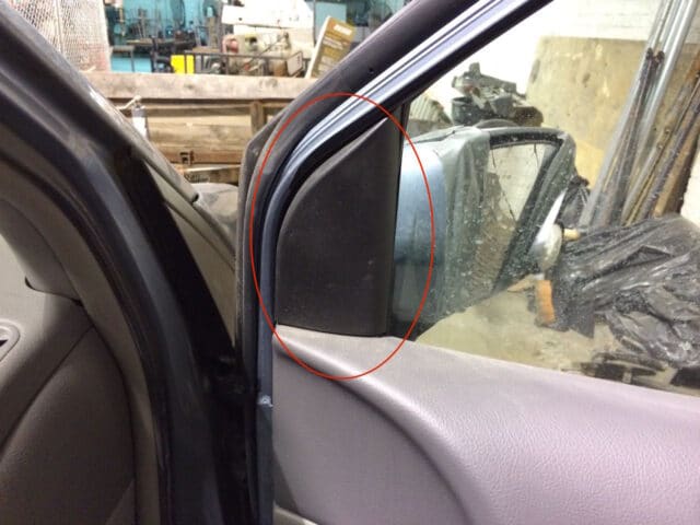 |
| We need to pop this panel off |
The panel is held in place by a clip on the top and a claw on the bottom:
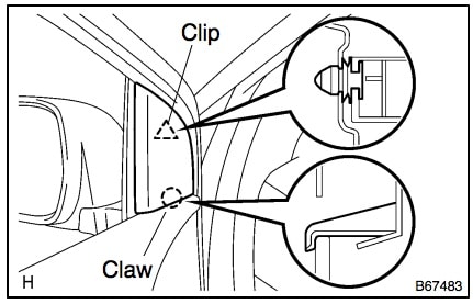 |
| Diagram of the plastic panel that covers the inside of where the mirror attaches to the van door |
To remove it I simply slid my fingertips along the window glass at the top of the panel and pulled straight out and it came free. This is what it looks like:
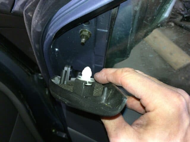 |
| Panel removed |
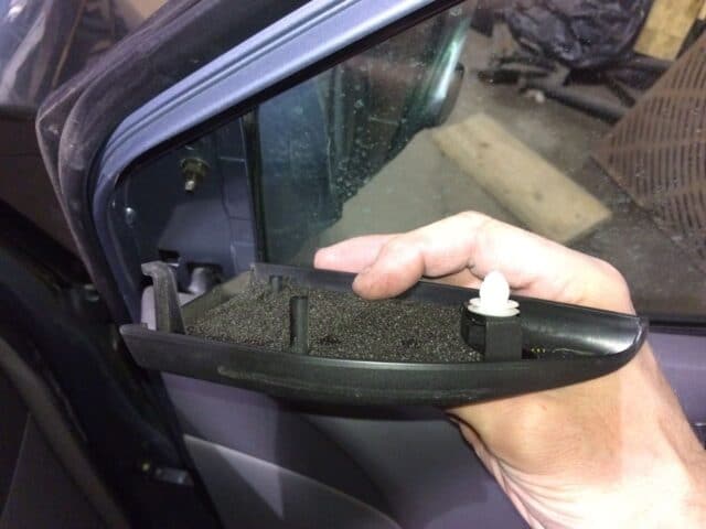 |
| Here you can see the claw at the bottom |
Unfortunately they hid the lower bolt and the wiring connector for the power mirror (and heating unit connectors) inside the plastic panel of the door so you must remove the plastic panel from the door. It’s not that bad though.
Step 3: Remove the door latch bezel and remove the screw hidden behind it.
The manual calls it the “Front Door Inside Handle Bezel Plug LH/RH.” The manual diagram wasn’t that helpful for me but here it is:
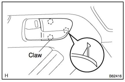 |
| Diagram of door handle bezel |
You can pry it free with an electrical-tape wrapped flat head screw driver with the latch pulled open:
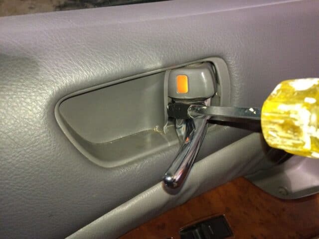 |
| Prying the door handle bezel free |
Here it is removed and you can see the prize that was hidden behind it, the phillips head screw that we will need to remove:
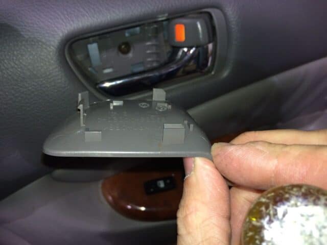 |
| The door handle bezel removed |
Remove the phillips head screw that was hidden behind the bezel and set aside for reinstallation later.
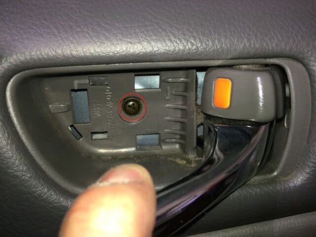 |
| Remove the phillips head screw hidden behind the door latch bezel |
Step 4: Remove the two screws from the top of the armrest.
The manual calls it the “Power Window Regulator Master Switch Assembly.” There is one screw down in the hand grip and one hidden under the arm rest compartment door:
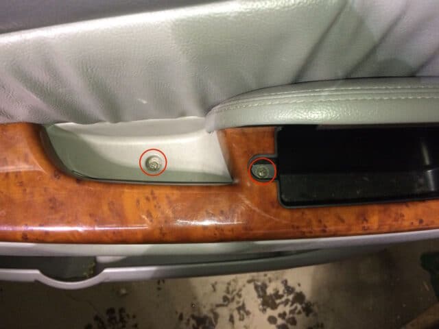 |
| Screw locations on the armrest |
Step 5: Remove the armrest cap.
Note: there are wiring connectors that will need to be released after this initial step. There is a spring clip on the end closest to the back of the van and a claw on the other end:
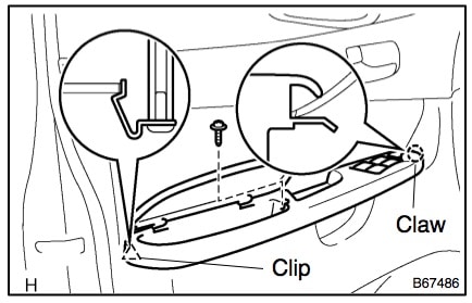 |
| Clip and Claw locations |
If you pry up the end opposite the power window controls you can see the metal clip as shown below:
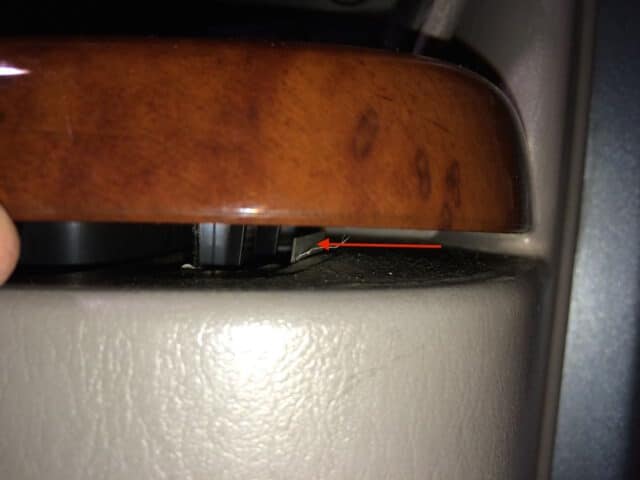 |
| Spring Clip Location |
If you take a flat screwdriver you can depress that tab shown above to easily release the cap:
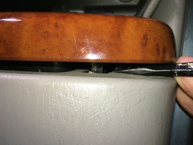 |
| Depressing the spring clip with a screwdriver |
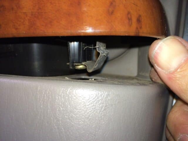 |
| Clip released |
Once the clip is released you can lift that end up and release the claw on the other end revealing the connectors for the power windows. Depress the tab on each connector (see red arrows below) and unplug them to release the armrest cover. Be careful where you lay this so you don’t scratch it up.
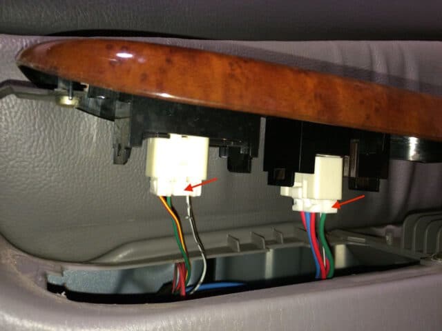 |
| Power window wiring connectors |
Step 6: Remove the clip on the rear edge of the door.
It has a screw-out center and then you can pop the entire clip out:
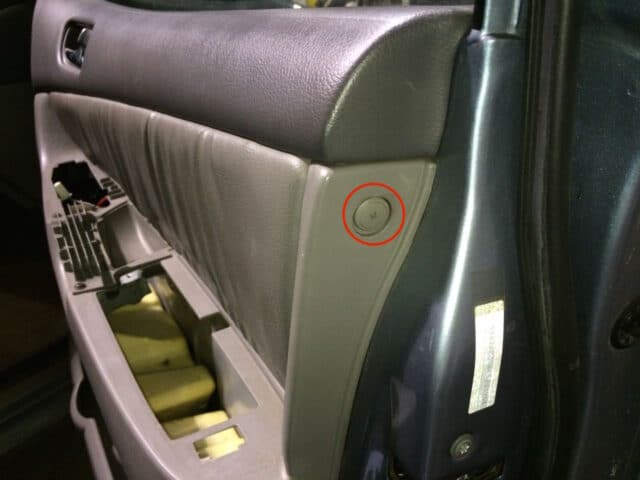 |
| Clip on rear edge of door |
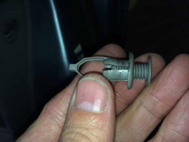 |
| Rear edge door clip removed |
Step 7: Remove the door handle sub-assembly.
The manual calls it the “Front Door Trim Board Sub-Assembly LH/RH.” There are three screws that hold this piece in place but you already removed the one that is at the bottom of the “cup” where you grab when shutting the door.
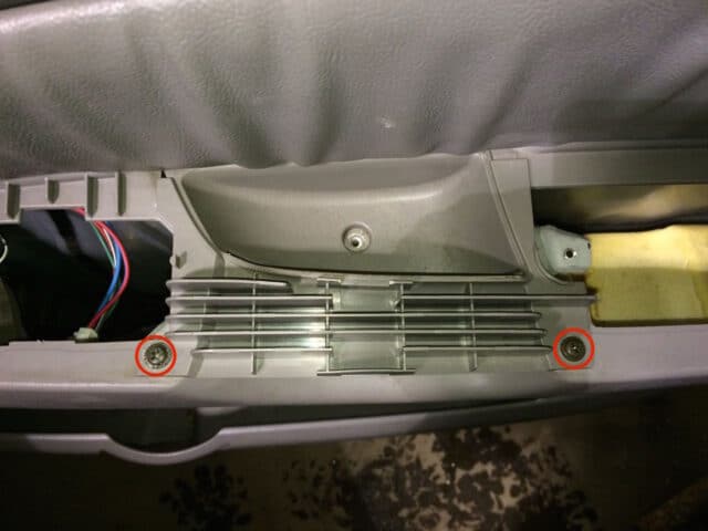 |
| The remaining 2 screw locations of the door handle sub-assembly (we removed the other one in step 3b) |
Here it is removed:
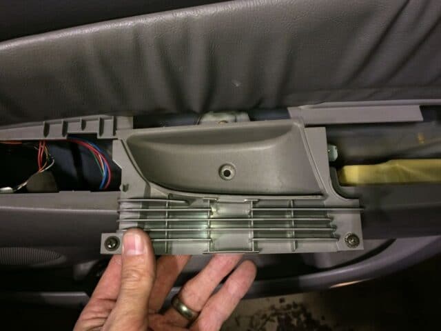 |
| Door handle sub-assembly removed |
Remove the screw that is below this piece:
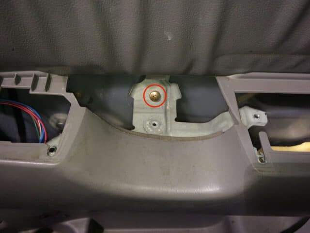 |
| Sub-Assembly sub screw |
Step 8: Disconnect the speaker wiring connector.
You can reach down in the open hole and disconnect it. Like all these wiring connectors there is a tab you must depress in order to separate the connectors:
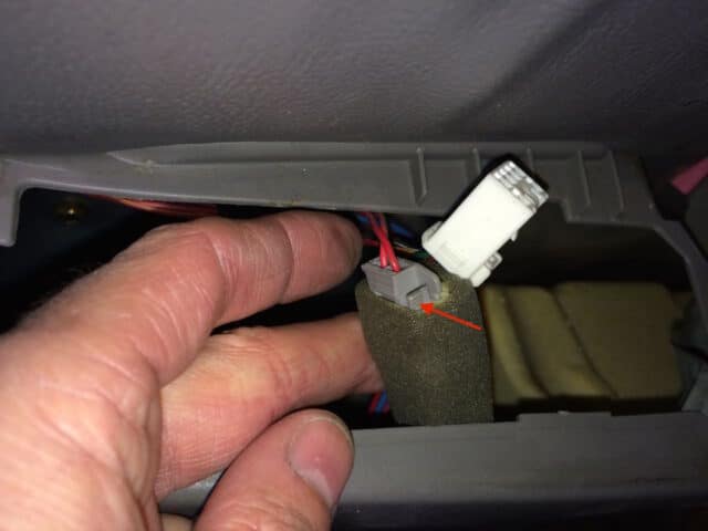 |
| Speaker wiring connector |
Step 9: Pop the interior door panel free from the door.
The panel “hangs” from the top of the door and then has snaps as shown in the diagram below (indicated by the 8 triangles):
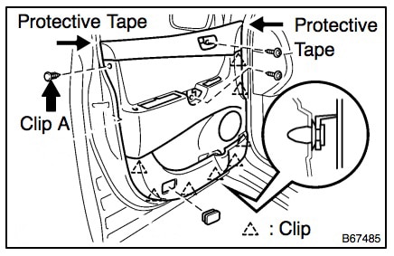 |
| Front Door interior panel clip locations |
I didn’t use any pry tools to pop the door panel free, I simply grabbed along the lower edge and gave it a good tug and it popped free. You must lift the entire panel up to unhook it from where it “hangs” from the top. The door panel will be retained by the cables that run to the inner door handle. The manual suggests disconnecting the cables but I do not recommend that. You can pop the entire plastic assembly free (by pushing it toward the inside of the van and then turning it and pulling it through the open hole:
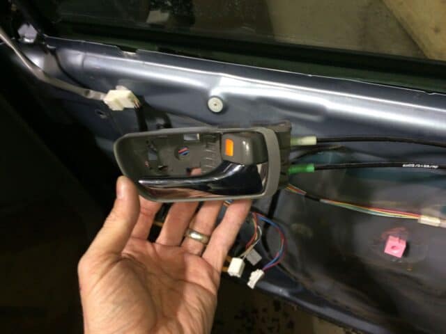 |
| Inner Door Latch removed from the panel |
Step 10: Disconnect the mirror’s wiring connector.
The female side of the connector is clipped to the door and will stay clipped to the door. Depress the tab on the male end of the connector and disconnect it.
 |
| Mirror wiring connector |
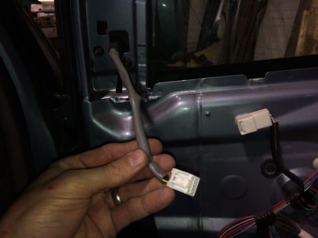 |
| Mirror wiring connector disconnected |
Step 11: Remove the 3 10-mm nuts that hold the mirror on the door.
I was able to loosen them with a standard 10mm socket (a deep well socket was not necessary). Here is their location:
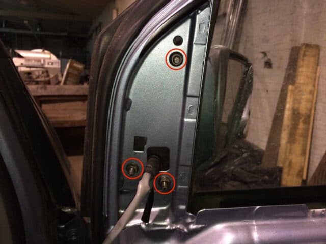 |
| Mirror nut location |
Once you have removed those three 10mm nuts the mirror will pull straight off the van and the wiring will pull out through the hole in the door.
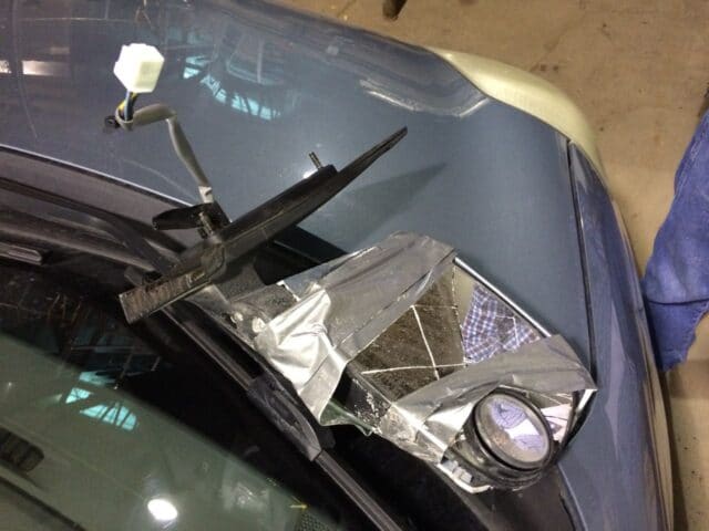 |
| The victim |
Step 12: Feed the wiring connector of the new mirror through the hole and bolt the new mirror on the door with the three 10mm nuts.
I don’t know the actual torque you are supposed to tighten these bolts with but I was aware that they are imbedded in plastic and although I wanted to make sure it was on there tight I didn’t want to break the plastic either.
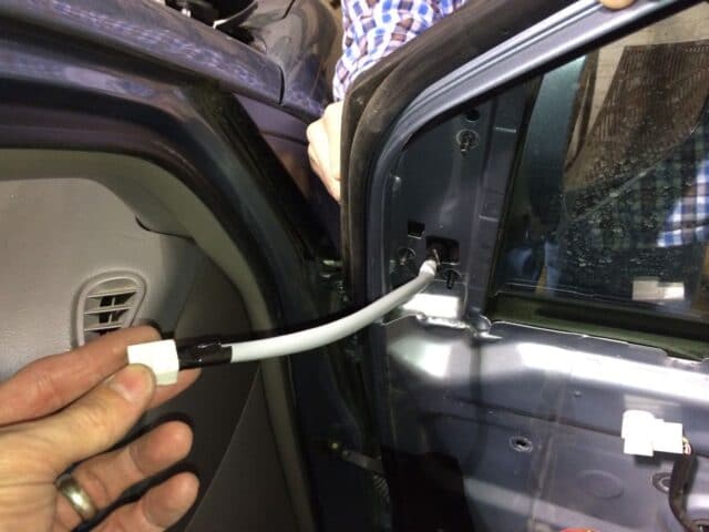 |
| New mirror ready to be bolted on |
Step 13: Reconnect the mirror wiring connector.
Make sure you hear it click so you know it has been inserted all the way.
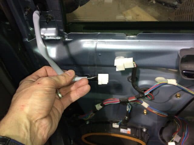 |
| Reconnect the new mirror wiring connector |
Step 14: Replace any broken clips on the back of the interior door panel.
I don’t have any pictures of this because I forgot to take them and there were no broken clips when I did this repair. I have links to the replacement clips in the parts list at the top of this post but now is the time to replace any of them if they have shattered when removing the door panel. The clips simply snap into place from the side. Also make sure they are all snapped into place or they will not line up with the holes in the door.
Step 15: Feed the interior door latch through the door panel and lock it into place.
If you twist it sideways it will easily go through the hole:
 |
| Reinserting the door latch into the interior door panel |
Seat the hinge end of the door latch assembly first and then lock it into place. Despite what it looks like in the picture below I do not have two left hands (sometimes it feels like it though and I’m right handed–LOL). I normally do these repairs solo but the owner of this van helped me with this repair and that’s his hand with the bracelet on it 🙂
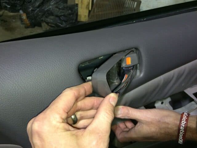 |
| Seat the hinge end of the latch into place first and then rotate it into place |
Step 16: Reinstall the interior door panel.
Remember that it “hangs” from the top and then snaps into place. Here you can see that I’ve hung it from the top and am lining up the clips:
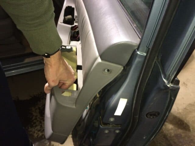 |
| Door panel hung on the top edge and lining up the clips |
Look along the side to make sure the clips are lining up:
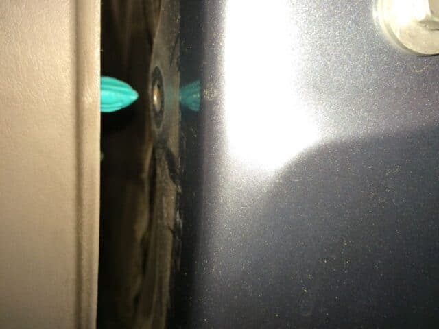 |
| Lining up the clips with the holes in the metal frame of the door |
Once you have the clips lined up I start pressing the interior door panel in place. I hit it in many places with the palm of my hand to “snap” it back in place. You ought to press all over because they won’t snap back together if you haven’t pressed in the area of the clip. Here’s a diagram of the clip locations for your refreshed memory (this time I circled the locations in red):
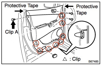 |
| Door panel clip locations |
Step 17: Reconnect the speaker wiring connector.
You should be able to easily locate it by looking down into the holes where the armrest are. All these connectors are different shapes so there’s no way you can reconnect them incorrectly, which is nice. It is easy to pick out the the female end of the speaker connector has foam wrapped around it (so it doesn’t make noise by vibrating against the inside of the door). Note there is a slot on one end of the connector that helps you line it up:
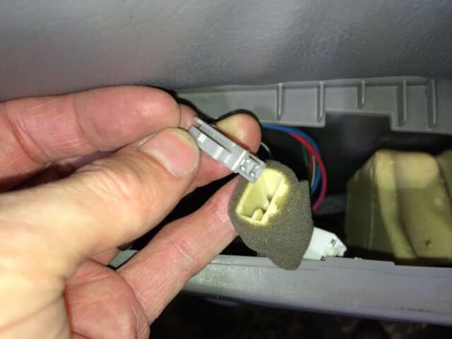 |
| Reconnecting the speaker connector |
Step 18: Reinstall the large phillips-head screw that was under the door handle sub-assembly.
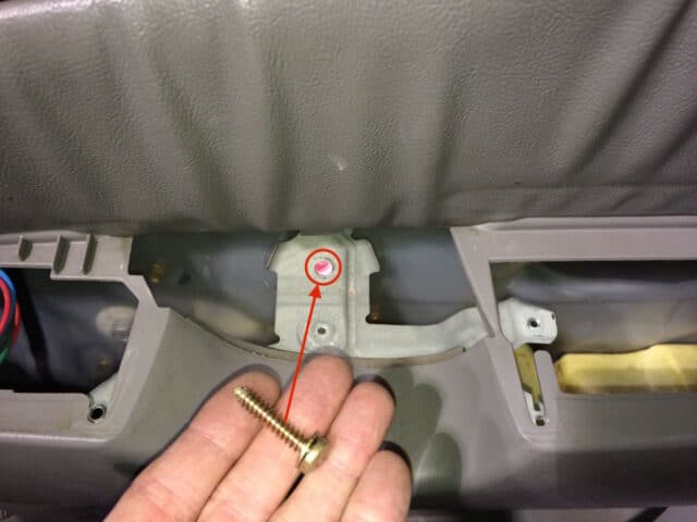 |
| Reinstalling the large screw under the door handle sub-assembly |
Step 19: Reinstall the door handle sub assembly.
It has 3 screws:
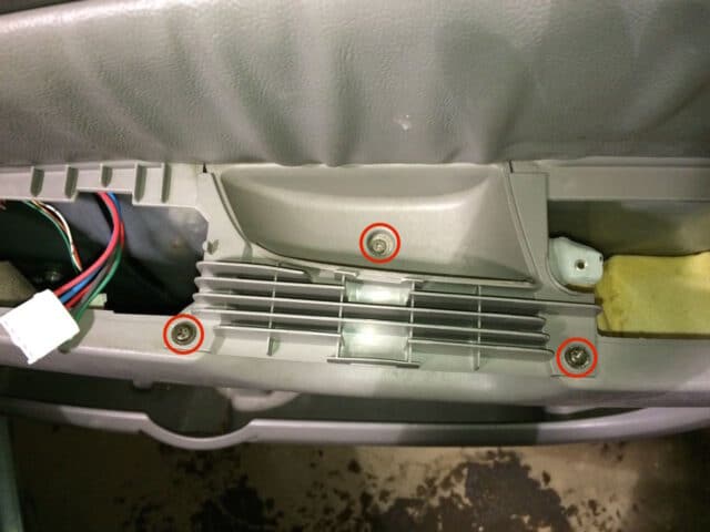 |
| Door handle sub-assembly reinstalled |
Step 20: Reinstall the door panel side “screw center” clip.
First make sure the door panel is lined up with the hole on the panel. When the center screwed out, insert it into the door panel and then screw the center in.
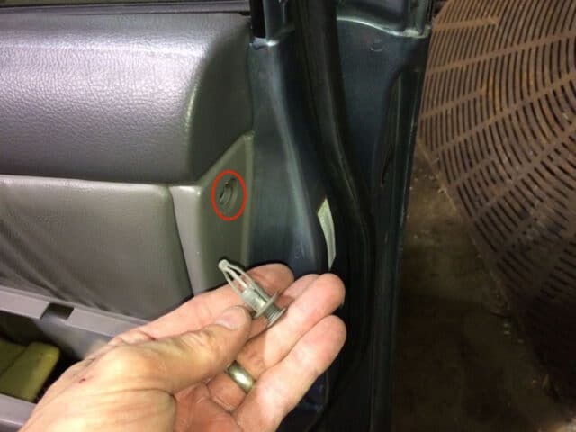 |
| Reinstall the door panel side clip |
Once the clip is inserted, screw in the center to lock it into place:
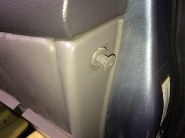 |
| Now screw in the center of the clip |
Step 21: Reconnect the two power window wiring connectors.
They are both different so you can’t reconnect them incorrectly:
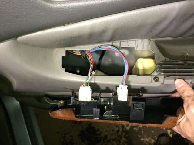 |
| Reconnect the two power window wiring connectors |
Step 22: Reinstall the power window hand rest assembly.
The end that is closest to the front of the van must be tucked in first and then snap the back end down. I used a flat-head screwdriver to depress the tab to make it easier to snap down (but the pictures were blurry). Here I am about to snap down the back end:
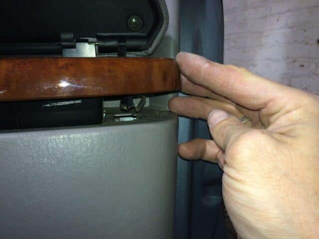 |
| Snapping the rear end down |
Step 23: Reinstall the last two screws.
One goes in the interior door latch assembly and the other goes under the arm rest compartment door:
 |
| Reinstalling the last two screws |
Step 24: Reinstall the door latch bezel.
I’m holding it the wrong way in this picture:
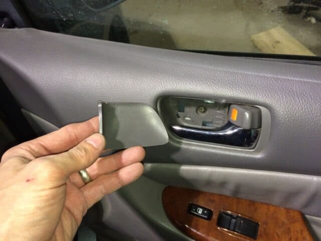 |
| Reinstalling the door latch bezel (here I’m holding the bezel backwards) |
You can easily snap it back into place with your fingers. Here the bezel is reinstalled:
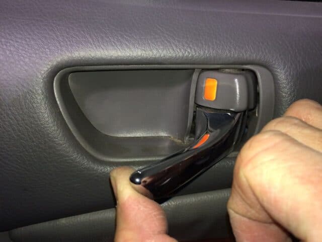 |
| Door latch bezel reinstalled |
Step 25: Reinstall the black plastic interior cover over where the mirror bolts to the door.
You must hook the lower tab first (scoot the wire that runs through the hole to the front to make room) and then snap it into place:
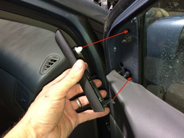 |
| The lower claw must go in the hole in the door next to where the wiring runs through |
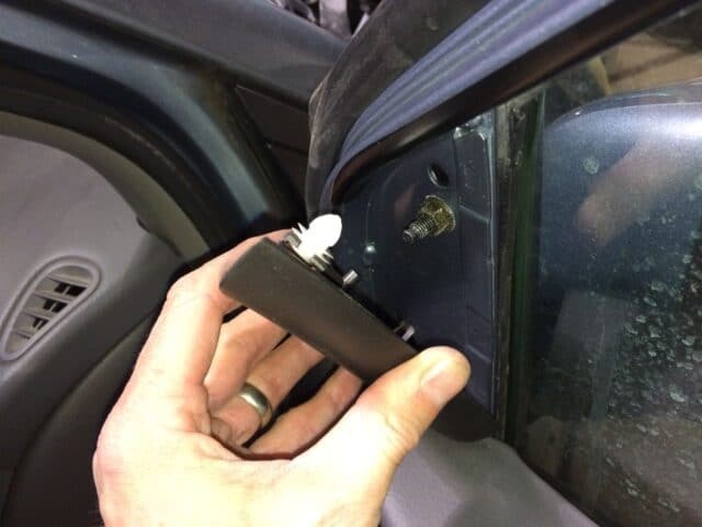 |
| The lower claw has been seated |
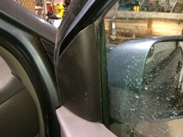 |
| Done! |
Now test out the power mirror (if you have that option):
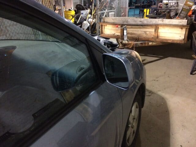 |
| Job complete and it looks nice |
Aren’t you glad you did it yourself!?!!? You just saved yourself at least $100 and it feels good to fix something yourself!
Amazon Associate Disclosure: As an Amazon Associate I earn from qualifying purchases. This means if you click on an affiliate link and purchase the item, I will receive an affiliate commission. The price of the item is the same whether it is an affiliate link or not. Regardless, I only recommend products or services I believe will add value to Share Your Repair readers. By using the affiliate links, you are helping support Share Your Repair, and I genuinely appreciate your support.
Related
(optional, but it’s good to have some on hand because they sometimes shatter when you pop off the interior door panel)
)
(if you really like tools and want to have “real” door panel removal tools–but you don’t need these, you can use an electrical-tape wrapped flat-head screwdriver too)


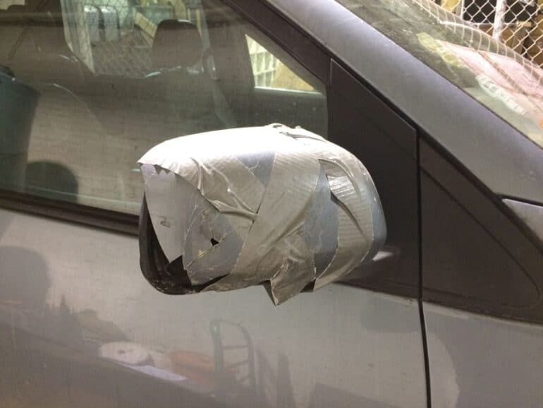
Hello Someone broke the drivers side mirror and kept going. 2008 Toyota Sienna LTD loaded. The mirror dangled and kept making noise like it was trying to adjust.(not close) Then the dashboard stopped functioning. No A/C, heat, mirror functions etc .Radio ,heated seats ,horn, seats all work. Replaced mirror with OEM connection fit perfectly. And still have same problem. checked fuses, relays, junction box. What am I missing ? can you please help me ! Thanks
Ok, I have some questions for you. After the mirror was knocked off, did the dashboard stop functioning right away? Was the dashboard working and then when you installed the replacement mirror, did that event cause the dashboard to stop working? What were the order of events?
Am very grateful you took the time to document these steps vs. a video. With a video I would have had to constantly stop, start and rewind while going through this process.
Thanks for the feedback Bob. I hope you got the help you needed to fix your Sienna.
Thank you very much for this very helpful guide. I was able to do it myself
Great to hear, good work on fixing your Sienna!
Thank you for excellent detailed instructions. It was perfect.
Great to hear Sameer, thanks for the feedback Good job on the repair.
There is a fold-in switch, and when pressed, the noise stops, the drivers mirror doesn’t move and the passenger mirror folds in. I wonder if I can access that switch? The van is always an hour away, so for now, I can only plot a “battle plan”.
I’d encourage you to look at the forums out there which discuss this issue extensively as I haven’t had any experience with this problem and I don’t have that automatic folding mirror feature on my van.
A 2007 Sienna drivers side mirror has a constant sound and vibration coming from it. I assume this is an adjustment motor of some type. It runs constantly…unless jarred. I could replace the mirror using these excellent instructions I suppose, but how do I know if it’s the mirror or a switch? Quite frankly I’d much rather pull connection to a switch(under dash?) Any thoughts would be appreciated.
Good question. I have not had any experience with that. I googled the problem and found many conversations on that topic. Does your van have the power fold-in mirrors? The only thing I can think of to narrow down the problem between the mirror or switch is to take both mirrors off and plug the opposite one into the side where the problem is occurring and see if it stays on that side or whether the problem moves–if the problem moves you know it is the mirror, if not, it’s the switch. Sorry I couldn’t be more help.
THANK YOU. I couldn’t have asked for better instructions. I now have a perfectly replaced mirror, and it only cost me fifty bucks for the part. You’re a lifesaver.
Thanks for the feedback Stephanie, I’m glad you found the help you needed.
Do you have instruction on the 2012-2015 model year?
I don’t have instructions for that new of a model. I would bet that it is going to be very similar to the the one I go over. You will need to remove the cover on the inside of the mirror and you’ll need to get into the door to disconnect the wiring harness. Those may be the same piece or they may be separate pieces.